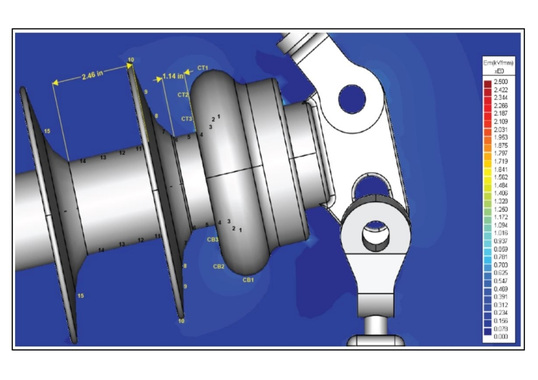
E-field modeling of insulator and hardware applications has become a valuable tool to ensure proper corona protection for a transmission assembly before submitting for laboratory testing or for installation and energization in the field. One of the benefits of completing E-field models is that multiple combinations of insulators, corona rings, shields and hardware can be evaluated in order to quickly and efficiently satisfy customer requirements. This can be done for new projects at the developmental stage or for troubleshooting existing applications that may have been applied without sufficient corona protection.
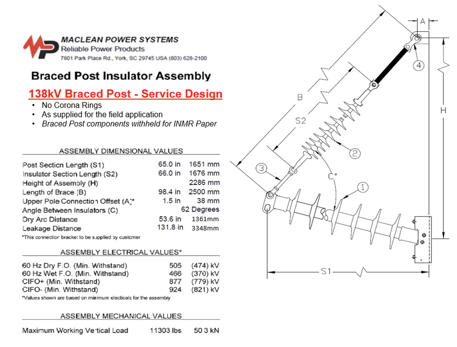
This edited contribution to INMR by Edward Niedospial, Technical Director – Transmission at MacLean Power Systems, defines a case study completed on a 138 kV braced post application that was originally designed and applied without corona rings. While it may have performed well, it no longer met today’s stricter corona performance criteria.
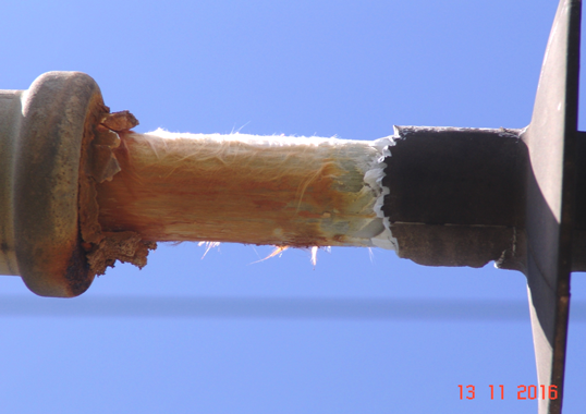
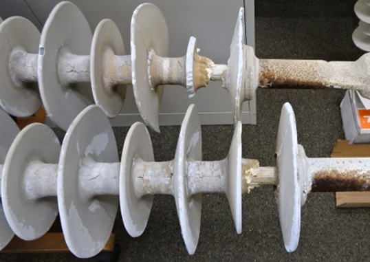
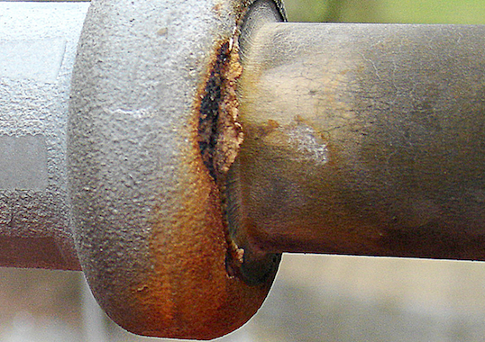
The subject 138 kV braced post model was designed and supplied without corona rings, as was the standard practice at the time, when corona rings were typically added mainly for 230 kV applications and above. Over approximately 16 years in service, some of these applications raised concern about corona related ageing of the polymeric sheath, specifically on the line post insulator of the braced post assembly. To determine the ideal corona protection for this braced post design, E-field modeling was employed to try various and compare different corona ring combinations.
E-Field Model Assumptions
• Test Lab Simulation
• Voltage applied to line end and hardware: 80 kV
• Voltage applied to tower and hardware: 0 kV (ground)
• Single phase at 22 ft ground clearance
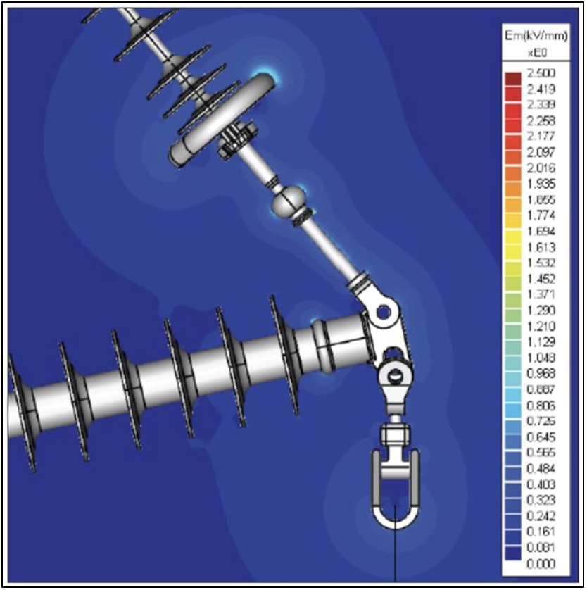
• 138 kV braced post (BP)
a) BP model with no corona ring
b) BP model with 8” corona ring (CR) on brace insulator
c) BP model with 8” CR on brace and 6” CR on line post insulator
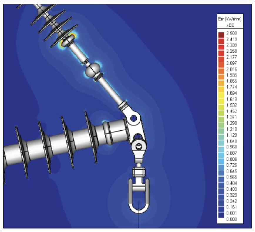
• The brace and line post insulators are connected using a hot line fitting, which is unique to this design. (Note: For this case study, this hotline fitting was not changed since the focus was on addition of corona rings, for easier upgrades of existing applications).
Objective
Model the ideal braced post arrangement to satisfy the recommended Industry performance criteria for E-field stress limits.
Performance Criteria
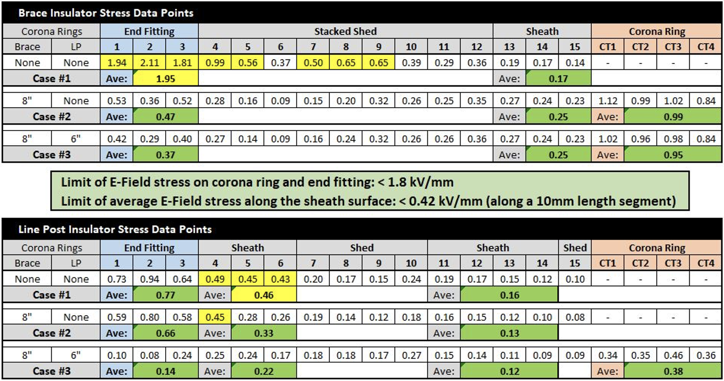
• Limit of E-field stress on end fittings and grading rings: 2.0 kV/mm
• Limit of average E-field stress along sheath surface: 0.42 kV/mm
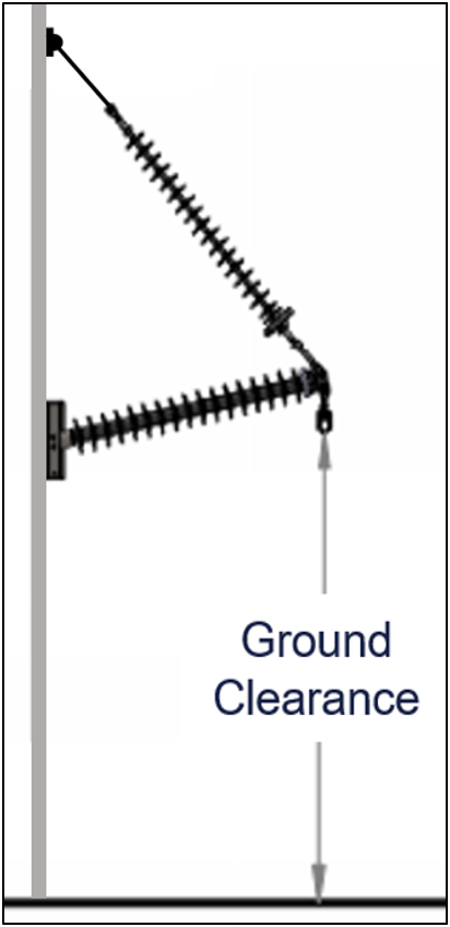
Note: Results and conclusions for the proposed 138 kV braced post models are specific to defined phase-to-ground clearance, as defined by the customer. The tighter the phase spacing, the higher the E-field stresses can become.
Case Study Background
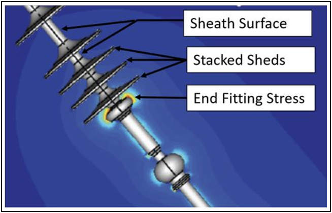
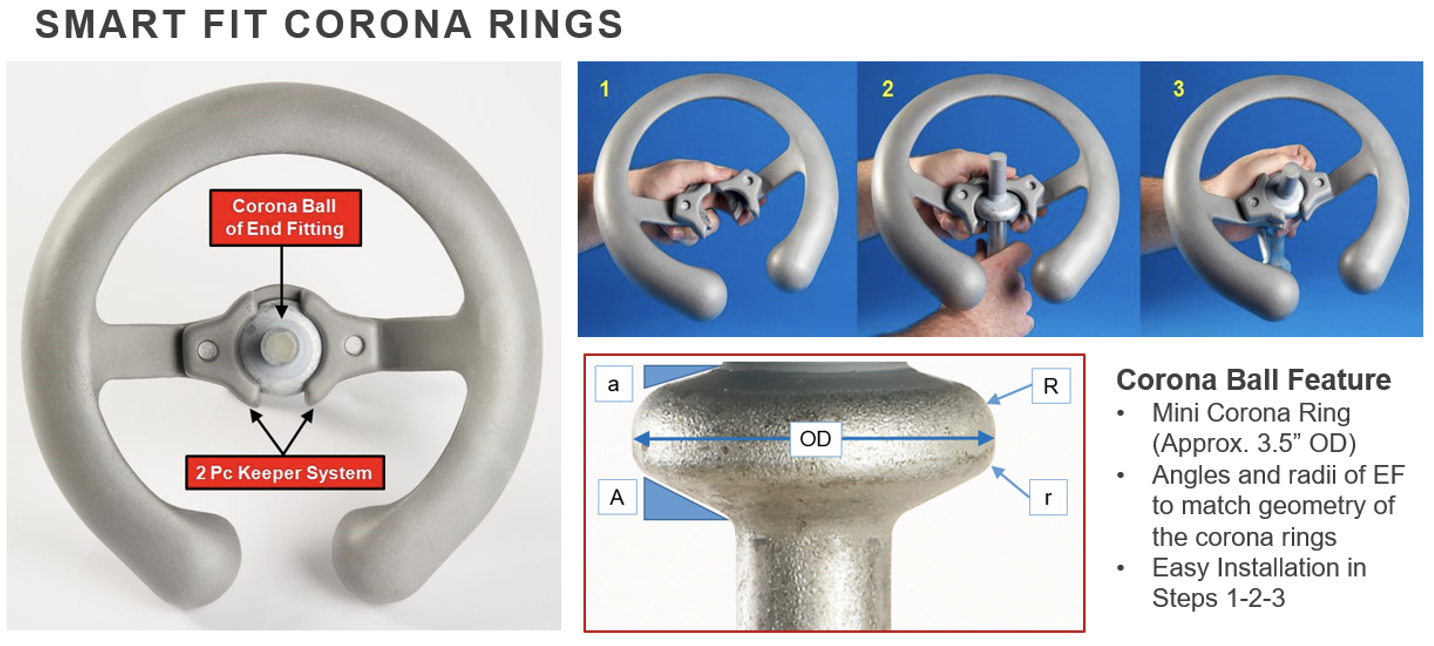
Stresses on the line post insulator are different than on the brace insulator. Since the brace, or suspension, insulator has stacked sheds, the sheath is protected from higher electrical stresses at the line end even without a corona ring. Moreover, the larger corona ball feature on the brace end fitting further helps reduce amount of stress on the sheath.
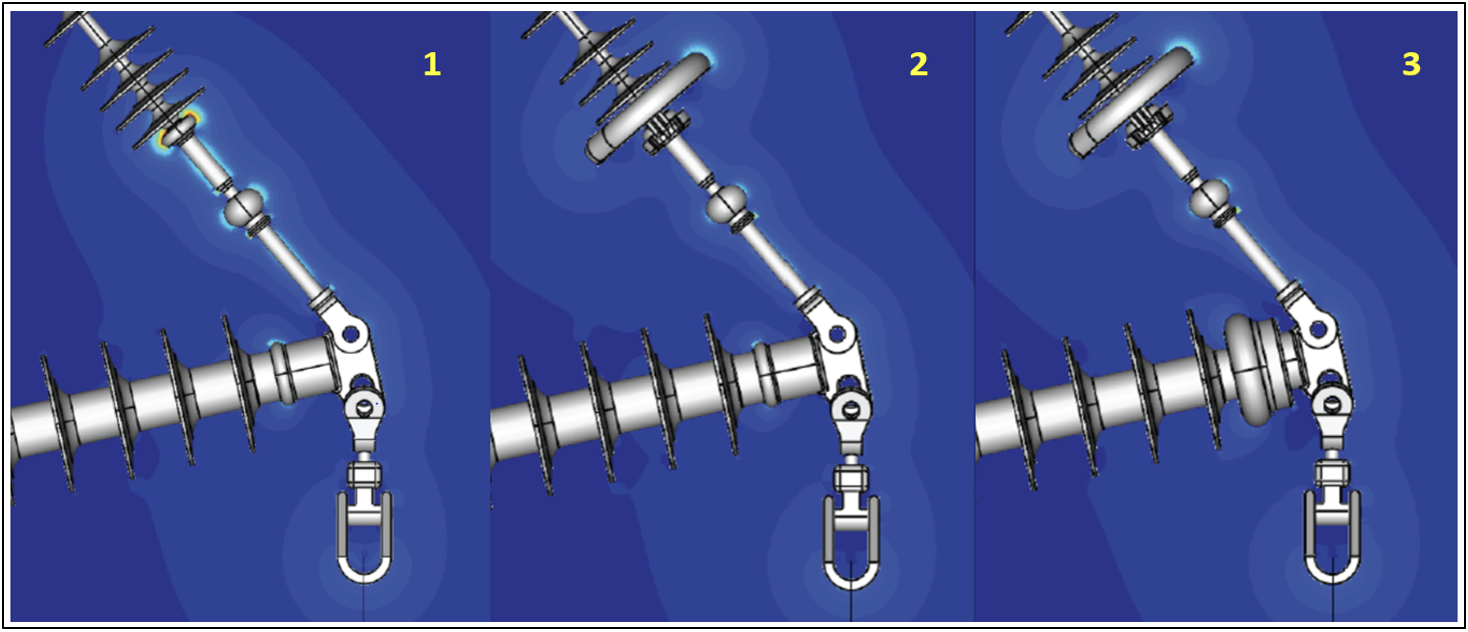
This case study will identify the E-field stresses for 3 different braced post configurations in order to determine the ideal corona ring applications for 138 kV braced post designs.
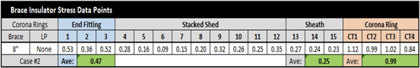
For well-defined comparable results, each configuration had measurements taken at the same positions along the insulator to observe the levels of stress. Data points were captured along the end fitting, sheath, sheds, and corona rings.

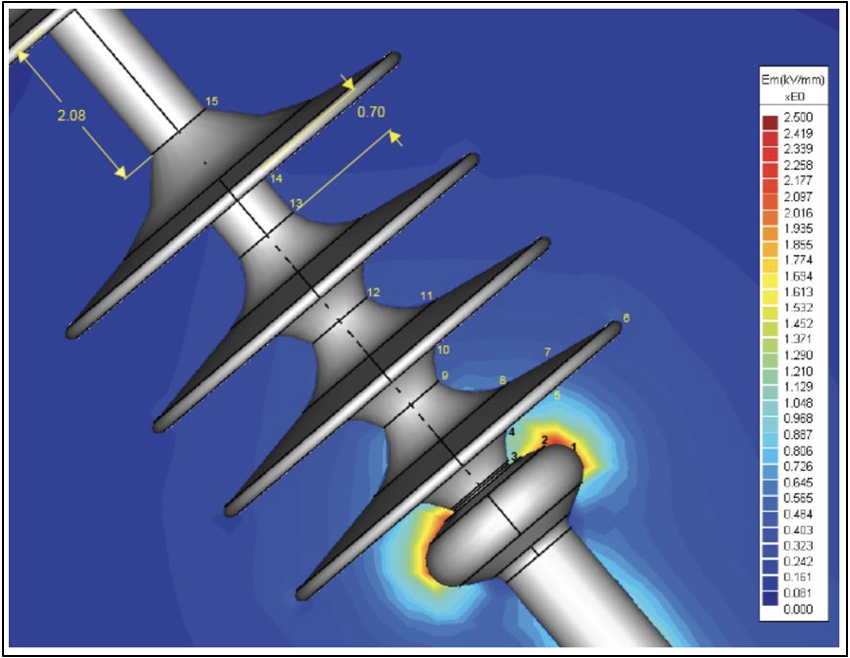
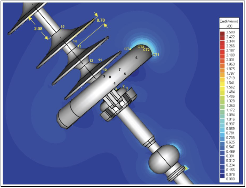
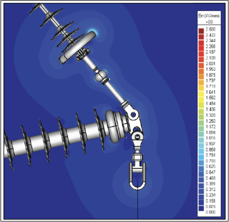
Configuration #1: 138 kV Braced Post, No Corona Rings
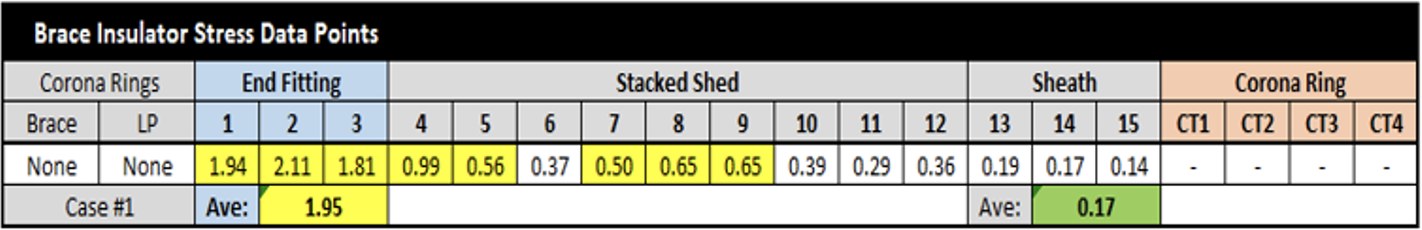
Brace Insulator
The average stress on the end fitting is high, with a max stress above the industry performance limit 2.0 kV/mm. Though this initially appears to be a concern, the stress is on the corona ball away from the silicone rubber; the presence of the stacked sheds minimize the impact this stress could have on the sheath. Therefore, there is no concern for premature aging of the sheath on this brace insulator.
• Average Stress on the End fitting = 1.95 kV/mm [Max Stress = 2.11 kV/mm]
• Average Stress on the Sheath Surface = < 0.17 kV/mm (measured beyond shed #3)
• No exposed sheath between shed #3 and end fitting.
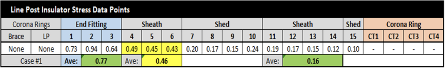
Line Post Insulator
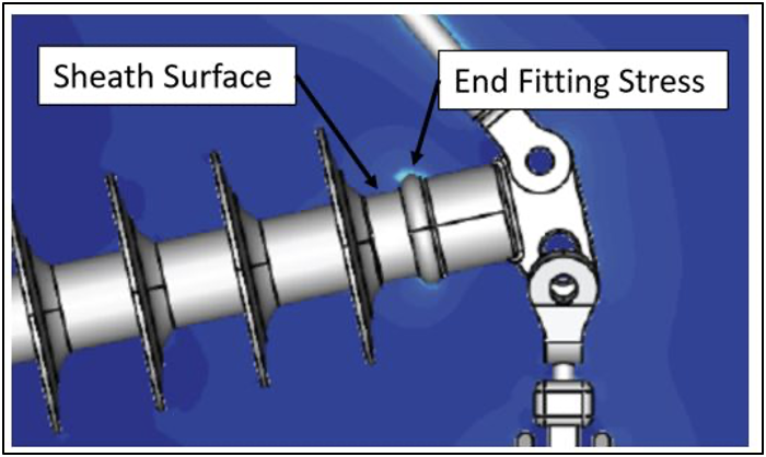
In general, the stresses are lower on the post than on the brace insulator above. The average stress on the end fitting is not an immediate issue. Since the stresses on the sheath are at the threshold value, there is concern of premature ageing of the sheath between shed #1 and the end fitting.
• Average stress on end fitting = 0.77 kV/mm [max stress = 0.94 kV/mm]
• Average stress on sheath surface (EF & shed #1) = 0.46kV/mm [max stress = 0.49 kV/mm]
• Stress on sheath surface (sheds #1 & #2) = < 0.16 kV/mm

Configuration #1: Final Observations of E-Field Analysis
Observations for Brace
• E-field stress focused on the EF corona ball feature, around entire EF, and some stress on the barrel.
• 1.95 kV/mm average stress on EF (above 1.8 kV/mm limit)
• No stress exposure on the sheath due to the stacked shed feature.
• Stress on first exposed segment of sheath at points 13-15 are below the 0.42 kV/mm threshold.

Observations for Post
• E-field stress focused on the top side of end fitting.
• Bottom of EF appears to be getting protection from clamp.
• Stress on EF is below the 1.8 kV/mm threshold.
• Stress on sheath at points 4-5 are above the 0.42 kV/mm threshold, potentially leading to premature ageing of sheath.
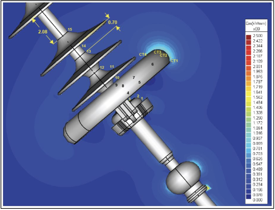
Configuration #2: 138 kV Braced Post – 8” Corona Ring on Brace Insulators Only
Brace Insulator
Addition of the 8” corona ring on this insulator corrects the high stresses on the end fitting, resulting in a brace insulator that is fully compliant with industry limits.
• Average stress on end fitting = 0.47 kV/mm [down from 1.95 kV/mm]
• Average stress on corona ring surface = 0.99 kV/mm
• Average stress on sheath surface = < 0.17 kV/mm
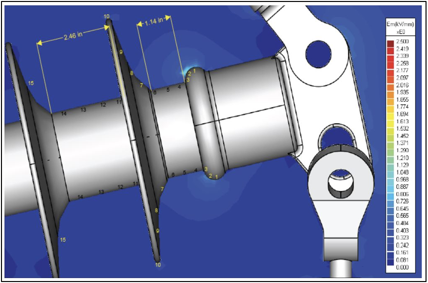
Line Post Insulator
There is some improvement to this insulator from addition of the 8” corona ring to the brace insulator. However, there is still some stress above the 0.42 kV/mm threshold, potentially being a source for premature ageing of the sheath near the end fitting.
• Average stress on end fitting = 0.66 kV/mm [down from 0.77 kV/mm]
• Average stress on sheath surface (EF & shed #1) = 0.33 kV/mm [max stress = 0.45 kV/mm]
Configuration #2: Final Observations of E-Field Analysis
Observations for Brace
• E-field seems to be focused on top side of corona ring, facing outside of BP.
• Some stress on connection hardware but still below the 1.8 kV/mm threshold.
• E-field stress moves from EF to corona ring.
• 75% improvement from EF to corona ring.

Observations for Post
• E-Field stress focused on top side of end fitting.
• Bottom of EF appears to be getting protection from clamp.
• 15% improvement on EF.
• 28% improvement on sheath.
• Still some concern of stress at point 4 on sheath
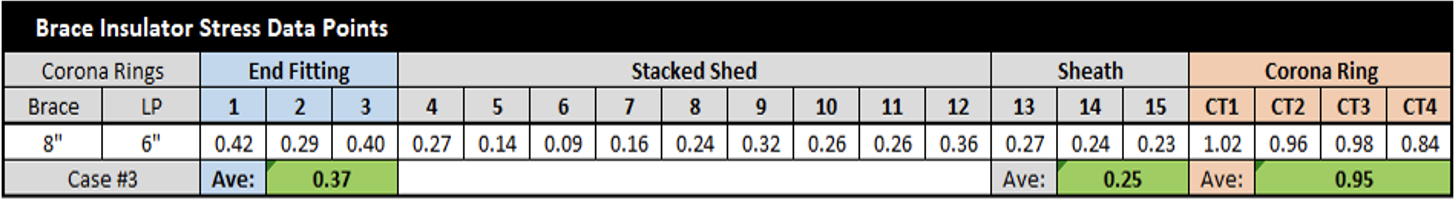
Configuration #3: 138 kV Braced Post – 8” Corona Ring on Brace & 6” Corona Ring on Line Post
Brace Insulator
Addition of 8” corona ring on this insulator corrects the high stresses on end fitting, resulting in a brace insulator that is fully compliant with industry limits.
• Average stress on end fitting = 0.37 kV/mm [down from 0.47 kV/mm in model #2]
• Average stress on sheath surface = < 0.2 kV/mm
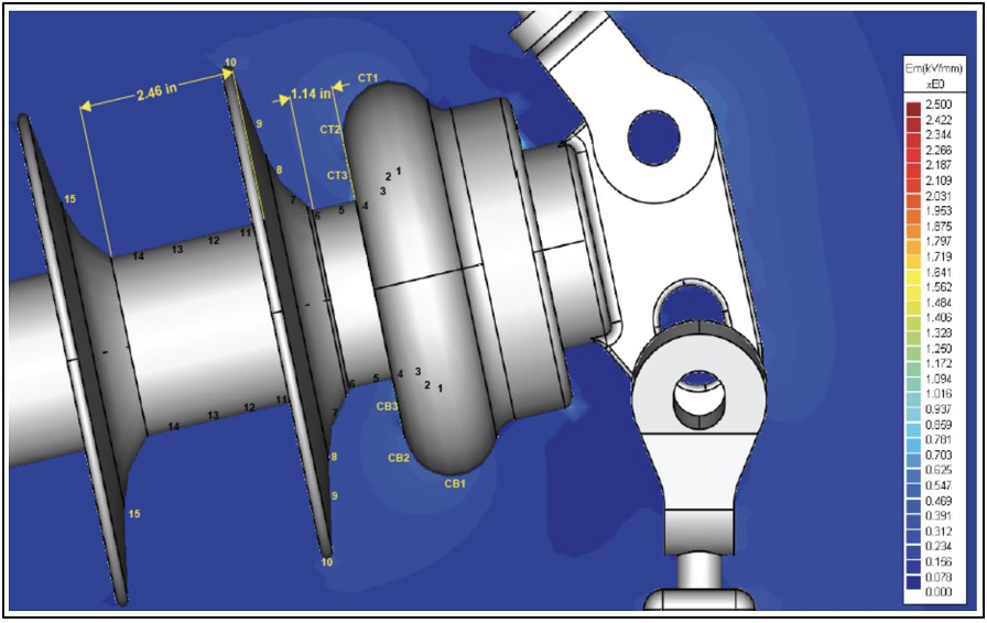
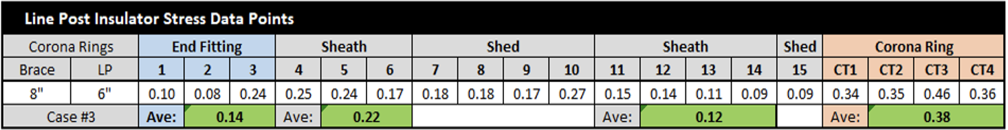
Line Post Insulator
Addition of the 6” corona ring onto this insulator, along with the 8” corona ring on the brace, provide the ideal corona protection for this braced post assembly. This configuration has the best performance, with no stresses above industry limits on either the end fitting or sheath of the line post.
• Average stress on end fitting = 0.14 kV/mm [down from 0.66 kV/mm in model #2]
• Average stress on corona ring surface = 0.38 kV/mm
• Average stress on sheath surface (EF & shed #1) = 0.22 kV/mm [down from 0.34 kV/mm]
Configuration #3: Final Observations of E-Field Analysis
Observations for Brace
• E-field stress focused on top side of corona ring, facing outside of the BP.
• Some stress on connection hardware but still below the 1.8 kV/mm threshold.
• E-field stress moves from EF to corona ring.
• 80% improvement from the EF to corona ring.

Observations for Post
• E-field stress is practically eliminated.
• 80% improvement in EF to corona ring.
• 50% improvement on sheath.
• LP compliant to all limits.
• Ideal corona protection for the braced post assembly
Conclusions
Historically, the corrective action for this 138 kV braced post case example may have been to just add the 8” corona ring onto the brace insulator, which does improve performance of the braced post assembly. However, upon reviewing E-field results in the tables below, even with the corona ring on the brace, the line post is still potentilly vulnerable to stresses at point 4 on the sheath at the end fitting connection point.
Major Take Aways
• The E-field model could be used to quantify with measurable data the differences (variations) from case to case of various corona ring combinations, putting forward solutions that are proven to work and meet customer expectations.
• The hot line fitting displaces the brace corona ring further from the line post, removing the shielding the brace corona ring would normally have for the line post. Hence the need for the line post corona ring.
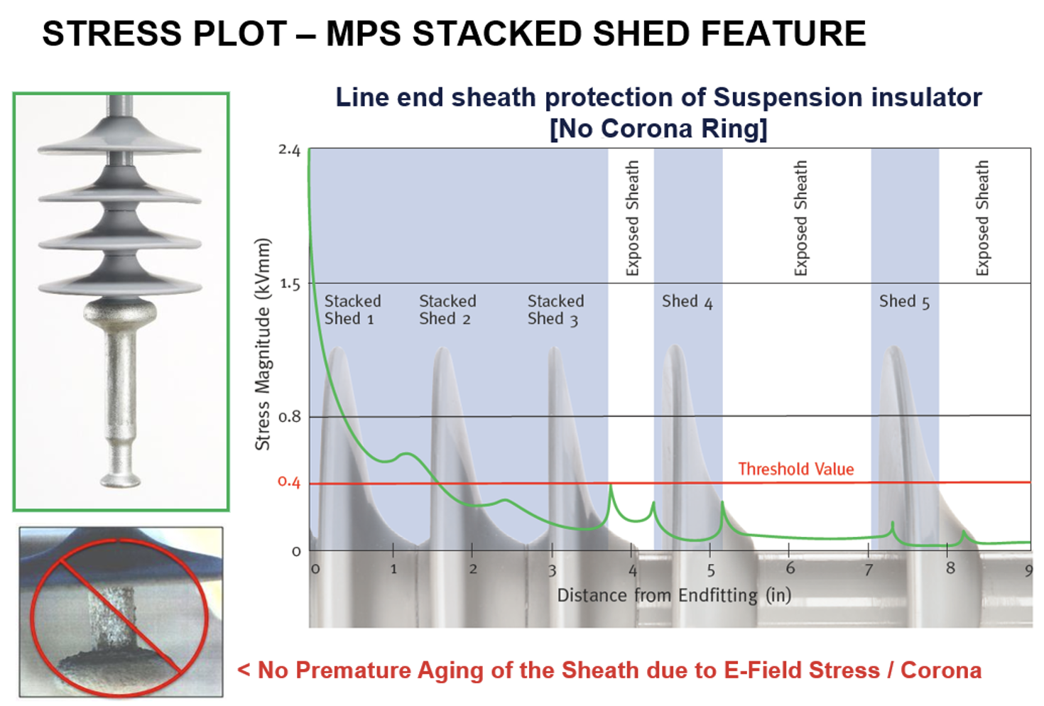
MPS Stacked Sheds protect the sheath of the suspension insulator from electrical stress and corona, preventing the onset of premature aging of the silicone sheath. This protection of the sheath is applicable with and without corona rings. This feature was developed to offset the effects of Water Droplet Corona.
[inline_ad_block]