Composite insulators have achieved high technical maturity with service experience and applications at all voltage classes. Nonetheless, to ensure reliable long-term operation, it is still necessary to optimize key compo-nents such as the end fittings, the FRP core and the housing material, in-cluding their various interfaces. Moreover, during such optimization, it is necessary to consider electrical, mechanical and other properties, such as ease of processing of materials and components or designs for special service environments.
Recently, there has also been an increasing trend toward tailor-made solu-tions that is pushing further development of polymeric materials for compo-site insulator and string designs. This has been triggered by strategic deci-sions in the power supply sector such as the move toward ultra-high volt-ages (> 800 kV, UHV) and expansion of HVDC transmission. At the same time, new material requirements are being defined in some utility specifica-tions and there is great interest in compact designs to promote public ac-ceptance of new lines. Maintaining the quality of composite insulators for expected long-term performance in such applications is yet another trend, especially since these insulators have transitioned from exclusive and ex-pensive to being regarded as cost-optimized commodities. These trends are also reflected in ongoing refinement of existing test methods to verify quality as well as in development of new test methods that aim to transfer service experience into the design stage of composite insulators.
This edited recent contribution to INMR by Pfisterer in Switzerland looked at current trends and aspects for development of new high temperature vulcanizing (HTV) silicone rubber formulations.


New Market Requirements
The following case study offers an example of developing a tailor-made, nitric acid resistant formulation of HTV silicone rubber material. The utility specification required that a cut section of the insulator needed to be stored for 100h at 30°C in 1 molar nitric acid. The material would pass if no crack formation was observed on the housing surface after a further drying period of 12h at 80°C. This requirement had been included in the specifica-tion after an incident of insulator failure initiated by housing material degra-dation, crack formation and exposure of the rod after strong corona dis-charges due to improper field grading. Nitric acid was generated under the specific service conditions that saw only low precipitation over the year. Such acid attack relates mostly to decomposition of fillers such as alumi-num trihydroxide (ATH) in HTV:
![]()
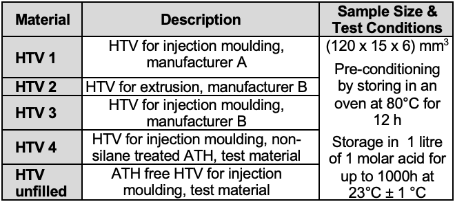
During the initial investigation, nitric acid (HNO3) resistivity was considered for commercially available as well as experimental formulations of peroxide curing HTVs (see Table 1). Tests were performed by storing three plate specimens of each material weighing circa 20 g for time intervals of up to 1000h in about 1 liter of 1 molar acid at room temperature (i.e. 23°C ± 1°C).
After defined times, the test specimens were extracted from the acid bath, dried at 80°C for 12h and evaluated, including:
• mass loss;
• tensile strength and elongation at break;
• visual appearance of degradation.
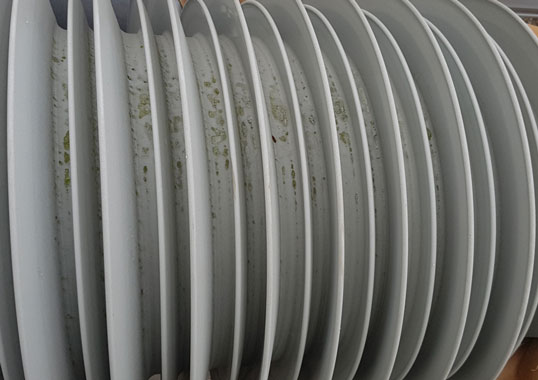
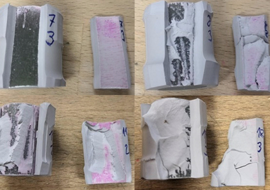
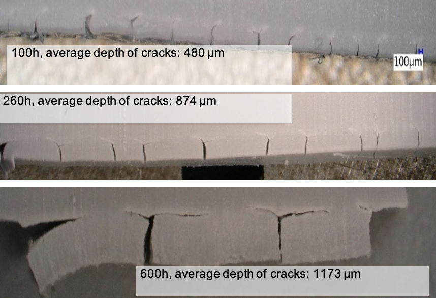
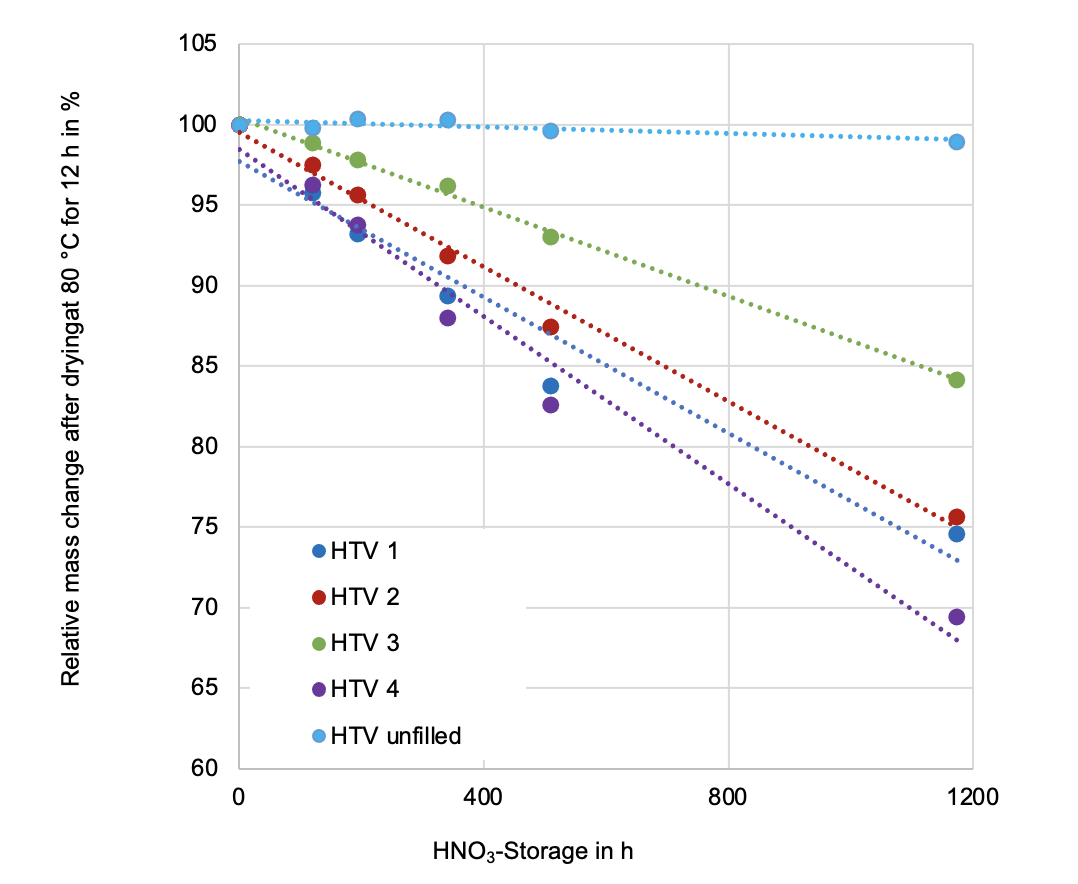
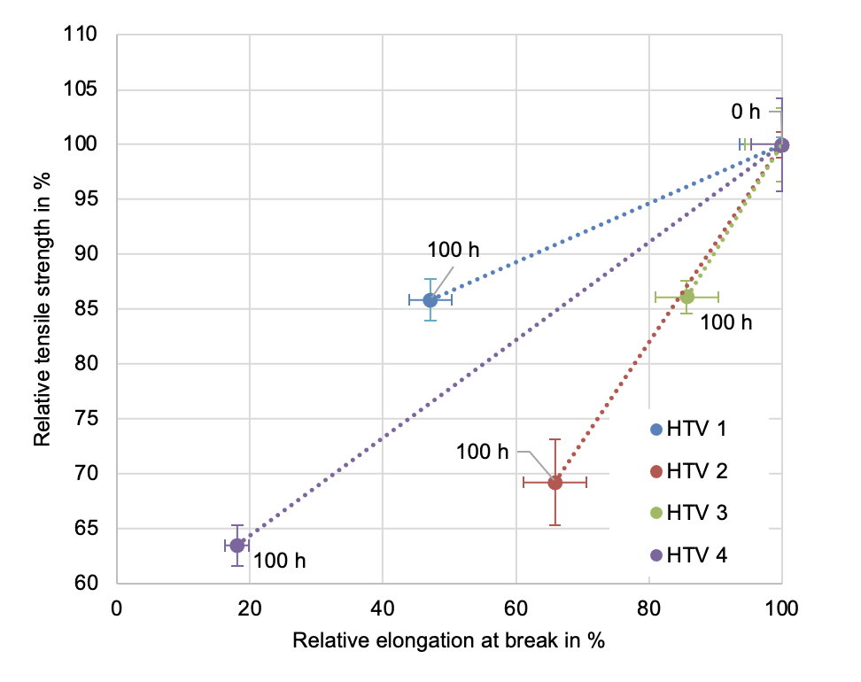
Material formulations with ATH filler showed significant crack formation and depth of cracks was measured (see Figs. 1 & 2). As expected, formation and depth of cracks for HTV 4 (with non-silane treated ATH) was most critical, whereas the unfilled HTV (i.e. without ATH) showed no crack for-mation. Other HTV formulations fell somewhere in between.
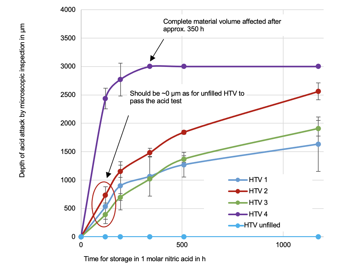
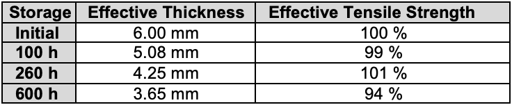
Figs. 3 & 4 show mass loss and tensile strength of the HTV specimens be-ing investigated. As expected, all ATH-filled HTV silicone formulations showed significant mass loss and decrease in tensile strength in about the same proportion as depth of crack formation. The unfilled formulation showed almost no mass loss and decrease in tensile strength (not shown). Interestingly, if effective cross-section reduction by cracking is considered in calculating tensile strength, the material still retains its initial tensile strength despite some deviation in measurement of depth (see Table 2). From this, it can be concluded that the bulk material is still fully intact. These initial investigations conclusively demonstrate the need to improve nitric acid resistivity of HTV formulations.
Given the mechanism of so-called ‘stress corrosion cracking’ that occurs during crack formation by nitric acid attack, three conditions must be fulfilled:
• Presence of a chemical substance that can corrode the material;
• A material susceptible to corrosion from this chemical substance; and
• Mechanical stress applied to the material.
From this, it becomes clear that the greatest potential lies in improving ma-terial formulation, either by replacing the ATH filler by an inert one, by op-timizing silane treatment, particle size and distribution of ATH filler or by implementing an additive that serves as a buffer for the acid. Most chal-lenging for development of an acid resistant HTV is achieving such optimi-zation without compromising other material properties, especially a high level of tracking and erosion resistance, mechanical properties and overall ease of processing. Moreover, all required material and design tests ac-cording to applicable IEC standards must still be passed.

Given a limited choice of different HTV components such as base polymer, curing agent and ATH fillers (including particle size, distribution and sur-face treatment), further additives were therefore evaluated with respect to:
• electrical properties (e. g. volume resistivity, tracking and erosion resistance);
• mechanical properties;
• multi-stress (e.g. accelerated weathering test);
• processing variables, especially viscosity, de-moulding ability, shelf life, and behaviour during storage.
Finally, an appropriate HTV formulation was found that successfully pass-es the acid resistance test, while also maintaining a high content of ATH filler (see Fig. 5).
Multi-Stress Evaluation of Nitric Acid vs. Tracking & Erosion Resistance
Polymeric materials in service are exposed to a combination of environ-mental factors (e.g. UV, acids) as well as electrical stresses (e.g. water droplet corona and dry-band arcing) that can simultaneously affect them. IEC TR 62039, defines 13 key properties, including minimum requirements, that must be fulfilled by polymeric materials for high-voltage outdoor applications. One of these is tracking and erosion resistance according to the test method described in IEC 60587. In the case of HTV silicone formulations, a high level of tracking and erosion resistance is related to ATH fill-er content. In parallel, nitric acid attacks and decomposes the ATH filler in an HTV silicone material. Therefore, the question arises of how previous nitric acid attack can affect the tracking and erosion resistance of these formulations.
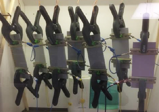
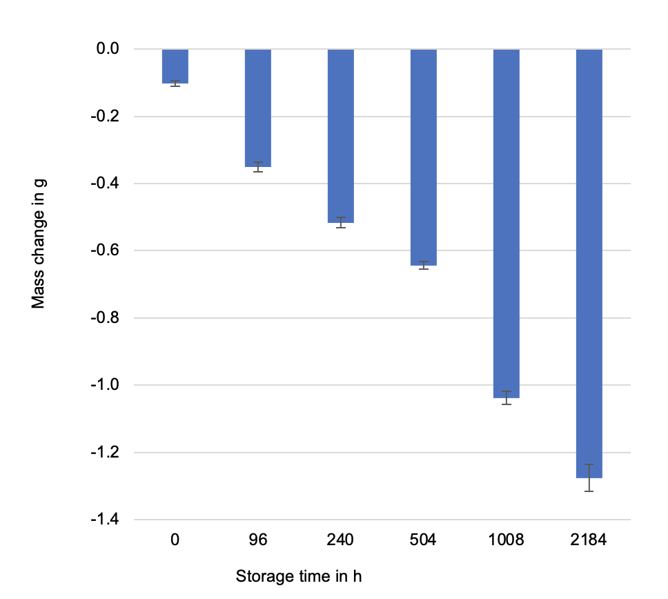
To obtain information on combined material stress by nitric acid attack and tracking and erosion resistance, plate shaped specimens of HTV 1 (as per Table 1) were pre-stressed by storage in nitric acid for different time inter-vals and subjected to the tracking and erosion test according to IEC 60587. A 0.1 mol/l nitric acid concentration in de-ionized water was used for pre-stressing. Five samples, sized 120 x 50 x 6 mm, were placed in a container with 1.3 l acidic solution and stored at 35°C for periods of 96h, 240h, 504h, 1008h and 2184h. Compared to the above mentioned ac-id concentration of 1 mol/l, a 10 times weaker nitric acid concentration was used to avoid severe crack formation on samples after the selected storage time, which could then have additional influence on tracking and erosion resistance. Moreover, ingress of nitric acid into test specimen might also result in an increase in surface conductivity, which could also have an undesirable effect on results of the tracking and erosion test. Weight of the samples was measured both before and after storage in nitric acid in order to detect any mass loss during storage.
A tracking and erosion test was performed according to IEC 60587, Method 1 (i.e. constant voltage application), Criterion A (i.e. leakage current criterion) at 4.5 kV AC stress. Given these parameters, the tracking and erosion test was deemed passed after a duration of 6h if none of the 5 specimens tested:
• exceeded a leakage current of 60 mA for 2 s;
• showed a hole (bulk erosion) due to intensive erosion;
• started burning.
Fig. 6 shows the test set-up at the start. Results were analyzed by evaluat-ing weight loss of the specimen during the test as well as the length, width and depth of any observed erosion. Fig. 7 provides findings on mass loss after nitric acid storage. As expected, according to Fig. 3, increase in mass loss with longer storage time could also be observed for the reduced nitric acid concentration of 0.1 mol/l.
Test results of the tracking and erosion tests after nitric acid storage for defined intervals are shown in Fig. 8. Evaluation of erosion depth is con-sidered the most characteristic parameter for silicone elastomers with this test.
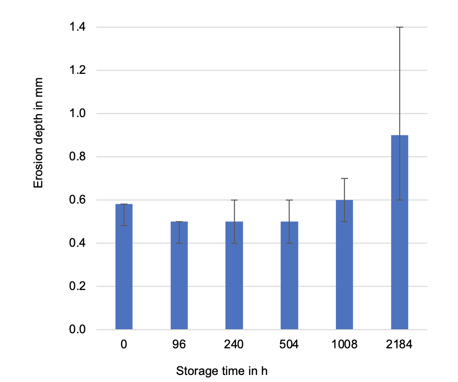
All samples passed the tracking and erosion test, regardless of their storage time in the nitric acid. Up to a storage time of 1008h, no change was observed in erosion depth while a storage time of 2184h resulted in a slight increase in depth. Visual inspection of test samples revealed an increase in superficial erosion (see Fig. 9)
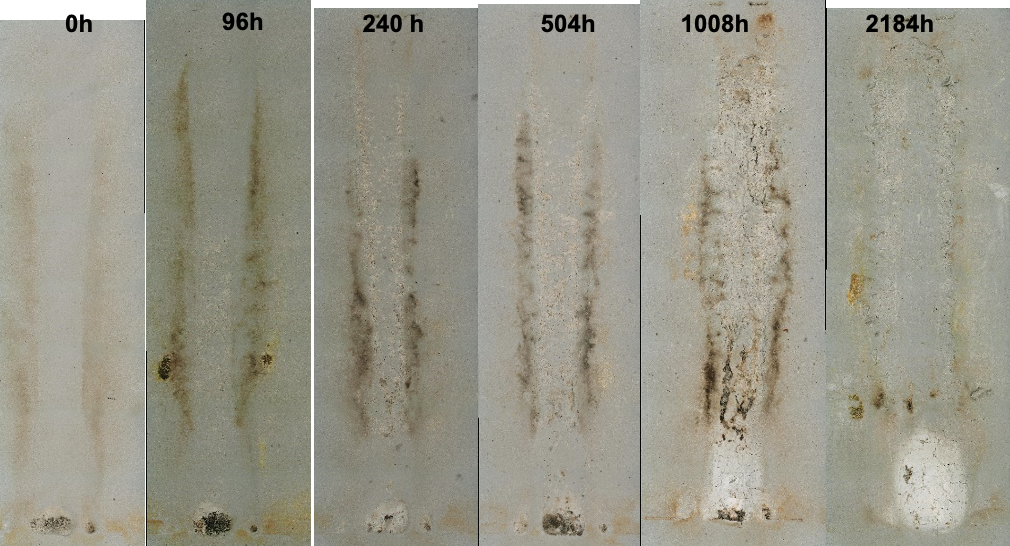
Moreover, area of superficial erosion increased with time in acid storage. While after 96h it only covered a small centre area between the electrodes, this type of erosion covered the entire area between electrodes after 1008h storage. After 2184h, a complete layer of silicone was eroded between electrodes. This effect is thought to be related to increasing intensity of nitric acid attack over the course of the storage period by locally dissolving ATH filler from the surface of the silicone rubber. Despite the acid at-tack, the standard HTV silicone formulation selected was still able to pass the tracking and erosion test. This was because the intact material volume was able to withstand the phenomenon of bulk erosion, i.e. the typical failure mode for such material formulations during a tracking and erosion test.

New Test Method to Evaluate Core-Housing Adhesion
An essential interface for composite insulators in service is that between the core rod and the housing. Only good adhesion can assure reliable long-term performance by avoiding risk of moisture accumulation and flashunder development at and along this interface.
Recent years have seen an increase in the number of reports of damage where the root cause related to such lack of adhesion and this has been observed for post, long rod and hollow core insulators. Given this negative experience, there have been extensive investigations into developing an up-to-now missing test method for quantifiable adhesion testing of the core-housing interface. This included an international round-robin test with the participation of different test laboratories. The so-called ‘pull-off test’ is based on the water diffusion test specified in IEC 62217 and includes a mechanical adhesion test. Initially, the water diffusion test was developed to evaluate hydrolysis resistance of an insulator core. However, due to the high quality of FRP rods these days, it further developed into a method to evaluate the quality of the interface. Here, the pull-off test was used for evaluating existing insulator designs to gain more experience with this new method. Moreover, it was decided to evaluate the suitability of new silicone formulations during development since proper chemical bonding as a key property also relates to housing material formulation.
A pull-off test was conducted:
• insulator segments were prepared, acc. to IEC 62217, cl 9.4.2, including 1 shed;
• the water diffusion test was conducted by boiling samples for 100h in salt water and performing a voltage test;
• the test criterion: leakage current at 12 kV < 0.1 mA;
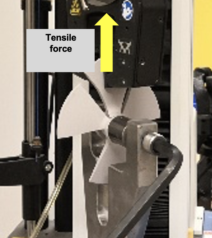
• afterwards, tensile tests were conducted perpendicular to the interface (see Fig. 10),
• the criterion: σ > 1.5 N/mm2,
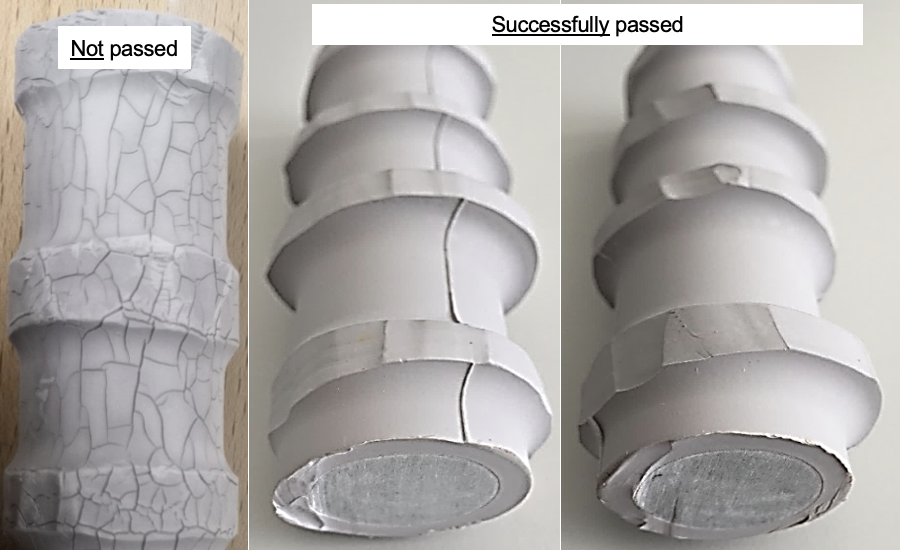
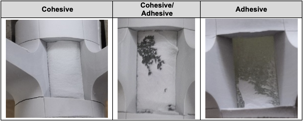
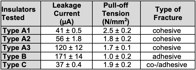
• an additional criterion was to evaluate type of fracture (see Table 3).
These tests involved two different types of long rod (A1, A2), one post (A3) and two types of hollow core insulators (B, C) from different manufacturers. In addition, HTV and RTV (room-temperature curing) silicone rubbers served as the housing materials (see Table 4). Insulator types A1-A3 passed the pull-off test, demonstrating the desirable cohesive interface fracture. While A3 showed higher leakage current, this was related to larg-er core diameter. Insulator type B failed the test by exceeding the leakage current criterion and having too low pull-off tensile strength. This was in line with the undesirable adhesive interface fracture observed. Insulator type C passed the test but showed a mixture of cohesive/adhesive inter-face fracture. Based on this initial investigation, the test method was seen to yield a correct and quantifiable evaluation of interface quality. Still, adapting the leakage current criterion to core diameter size is probably necessary.
In a next step, this new method was applied during selection of a housing material in respect to sufficient interface adhesion. A total of 18 different HTV formulations were investigated using the pull-off test. Sample insula-tors were manufactured by injection moulding different material formula-tions onto FRP cores with a diameter of about 18.6 mm. Using identical conditions and designs for production of these sample insulators allowed direct comparison of leakage current and pull-off tension. Fig. 11 shows examples of the leakage current measurements obtained.
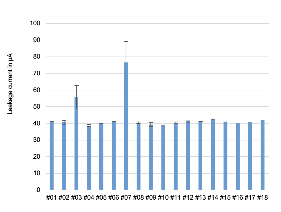
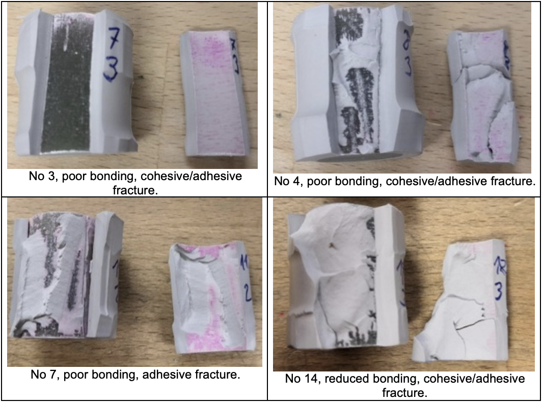
Test results for samples 3 and 7 showed significantly higher leakage cur-rents and a subsequent manual adhesion test confirmed lack of adhesion in these samples. However, unsatisfactory adhesion was also evident from the rod surface of sample 4 and to a lesser extent for sample 14, although not recognizable from the leakage currents (see Table 5). This was at-tributed to localized reduction in adhesion, which did not have an impact over the entire 30 mm length of the specimen and increased leakage cur-rent due to accumulation of moisture at the interface. In summary, the test method was deemed suitable to evaluate new housing material formulations during their development.
In another example, a different FRP rod supplier was evaluated and the pull-off test used to confirm proper adhesion between housing and core. Preliminary investigations confirmed suitable properties, according to IEC 62217. The FRP rods passed the water diffusion test as well as adhe-sion with the standard housing material in a manual adhesion test. Nonetheless, insulator samples showed unexpectedly high leakage currents (in the range of ~200 µA versus the expected ~60 µA). The pull-off tension of ~2.0 N/mm2 was in the expected range above 1.5 N/mm2.
Additional evaluation of type of fracture showed proper adhesion with good chemical bonding. Since the housing material was a standard formulation that also passed this test with the currently used rods, the only root cause could be some chemical interaction between the rod surface primer-housing material with the salty solution during boiling. The question then arose whether the new rod supplier would pass the pull-off test. Despite exceeding the leakage current criterion, proper adhesion was confirmed with the pull-off tests, which was the main goal of the investigation. To generate an overall evaluation of the suitability of this test method, all test-ed long-rod insulator samples with HTV housing were presented so as to correlate leakage current with pull-off tension, with distinction made be-tween cohesive and adhesive fractures (see Fig. 12).
Overall, there was no clear correlation between pull-off tension and leak-age current for the long-rod insulators investigated and no conclusions about type of interface fracture could be drawn. Correct interpretation of leakage current is regarded as challenging since this is an integral parame-ter influenced by the test arrangement in general and by sample dimen-sions (i.e. shank diameter) in particular. Any analysis of potentially exces-sive leakage currents, must identify and take into account the relative con-tribution by the FRP rod, the housing and their interface
.
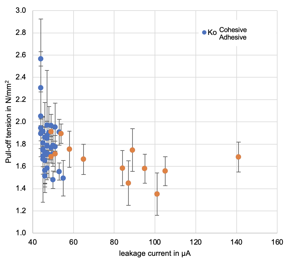
In conclusion, in order to assure proper evaluation of the results from the newly developed pull-off test, the combination of leakage current, pull-off tension and type of interface fracture are all meaningful parameters to con-sider. Further experience will need to be gained to determine suitable limits. Currently, this test is under consideration for standardization in IEC 61109 as a product standard for composite long rod insulators.

Summary & Conclusions
Current trends in composite insulator technology relate to growing demand from UHV and HVDC applications. Another factor are special requirements now found in some utility specifications that may require new product de-velopment or distinct material properties, e.g. a nitric acid resistant HTV formulation.
To maintain the required high level of quality of composite insulators and to assure expected reliable long-term performance, new test methods are now under development and being considered for standardization. These are demonstrated by the example of the newly developed pull-off test to evaluate proper core-housing interface bonding. Composite insulators have been used for decades yet remain technically exciting products with potential for continuous improvement.

References
[1] C. Baer, F. Schmuck, J. Strumbelj, E. Tinner, J. Lachman, S. Kornhuber, J. T. Loh: Technical Demands to Improve Today`s Composite Insulator Reliability, Paper B2-221, CIGRE Centennial Session 2021
[2] J. Strumbelj, C. Baer, J. Lachman, F. Schmuck: Application of Multi-stress Test Methods to evaluate To-day`s Composite Insulator Reliability, Paper B2-669, CIGRE Session 2022
[3] K. O. Papailiou, F. Schmuck: Silicone Composite Insulators, Materials, Design, Applications, Springer, Berlin, Heidelberg, 2013
[4] J. Lachman: Lessons from 25 Years’ Experience Testing Polymeric Insulators, INMR World Congress, Tucson USA, October 2019
[5] I. Gutman, J. Lundengard, C. Ahlrot: Need of standardized adhesion test for composite insulators: lesson learnt from service experience, 20th Symposium on High-Voltage Engineering (ISH), 2017
[6] C. Ahlrot, P. Aparicio, A. Berlin, T. Condon, J.-F. Goffinet, I. Gutman, K. Halsan, R. Radosavljevic, K. Varli, K. Välimaa: New test procedure intended to evaluate adhesion of core/housing interface of composite insulators”. CIGRE D1-303, CIGRE Session 2020
[7] I. Gutman, C. Ahlrot, P. Aparicio, A. Berlin, T. Condon, A. Dernfalk, J.-F. Goffinet, K. Halsan, K. Kleinekorte, J. Lundengård, M. Radosavljevic, P. Sidenvall, S. Steevens, K. Varli, K. Välimaa: Development of Innovative Test Procedure for Evaluation of Adhesion of Core-Housing of Composite Insulators: from Root Cause of Failures in Service to Reproducible Test Procedure CIGRE Science & Engineering, N°20 February 2021
[inline_ad_block]