In 2016, there was a single-phase fault resulting from the mechanical failure of a polymeric insulator on a transposition tower of the 400 kV Caruachi – Macagua Line in Venezuela. The failure was the direct result of a brittle fracture due to not installing corona rings during construction.
This edited past contribution to INMR by transmission expert Cristian H. Gutiérrez Aguirre highlighted the importance of corona rings at this voltage as well as the need for proper visual inspection by linemen and technical staff.
The first transmission lines in Venezuela went into commercial operation in early 1969 and were built using glass and porcelain insulators. Application of polymeric insulators at 400 kV began in 1998 and by the time of this incident they were installed on more than 2500 towers along 980 kilometers of lines, representing about 23% of the country’s entire transmission system. The failure due to brittle fracture described below documented the factors that contributed to this incident considering: period in service, failures of materials, absence of key accessories such as corona rings as well as external factors and environmental pollution that over time can reduce insulator life expectancy.

The 400 kV Caruachi – Macagua Transmission Line is located in the Puerto Ordaz area of Venezuela and interconnects the Caruachi and Macagua II Hydroelectric Power Plants. It is 28.6 km long with 69 towers over completely flat land flat between 80 and 90 m above sea level. It has four conductors by phase (model ACAR 1.024.5 MCM 30/7) and was energized in December 2003.
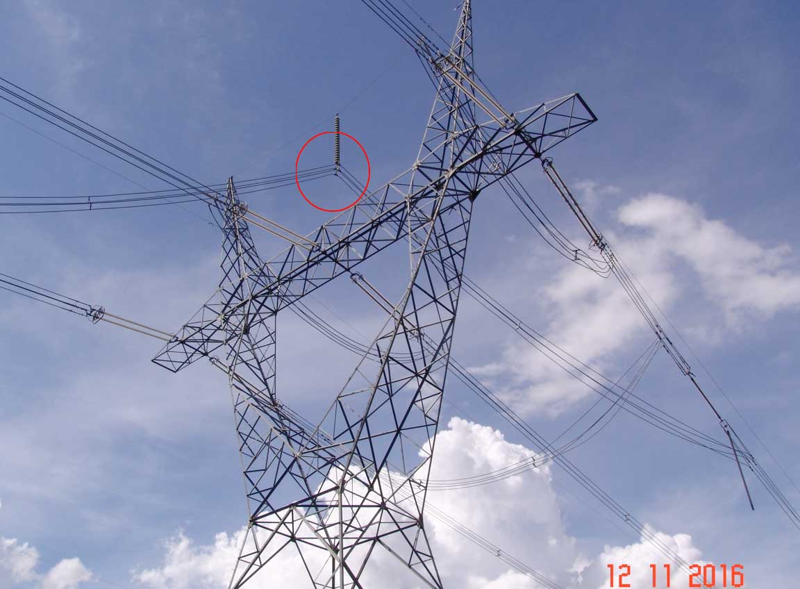
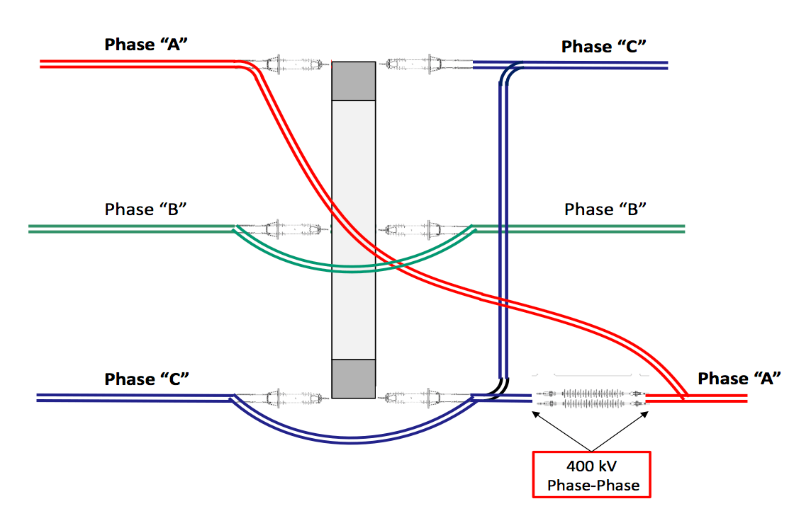
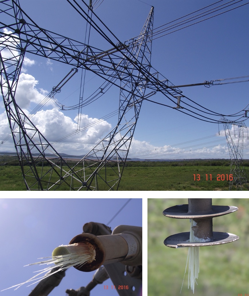
On November 12, 2016 at 10:20 am, substation maintenance personnel reported to the Regional Control Center a loud noise in dead-end tower No. 4. It was also reported that an insulator was broken and detached. Immediately, Transmission Line Maintenance personnel moved to the site and found that an insulator that serves as the retention element between phases A and C was broken and detached at one of its ends. Fortunately, the conductor had not fallen since it was in a double chain arrangement. Initially, the insulator was inspected using binoculars, De-energization of the line was requested because significant damage was detected in the insulator bar that was supporting the mechanical load of the four conductors, as shown below. It can be seen that the failed insulator is supporting, in parallel, the mechanical traction exerted by the conductors of phases A and C. Consequently, the double polymeric insulator arrangement is operating at 400 kV phase-phase.
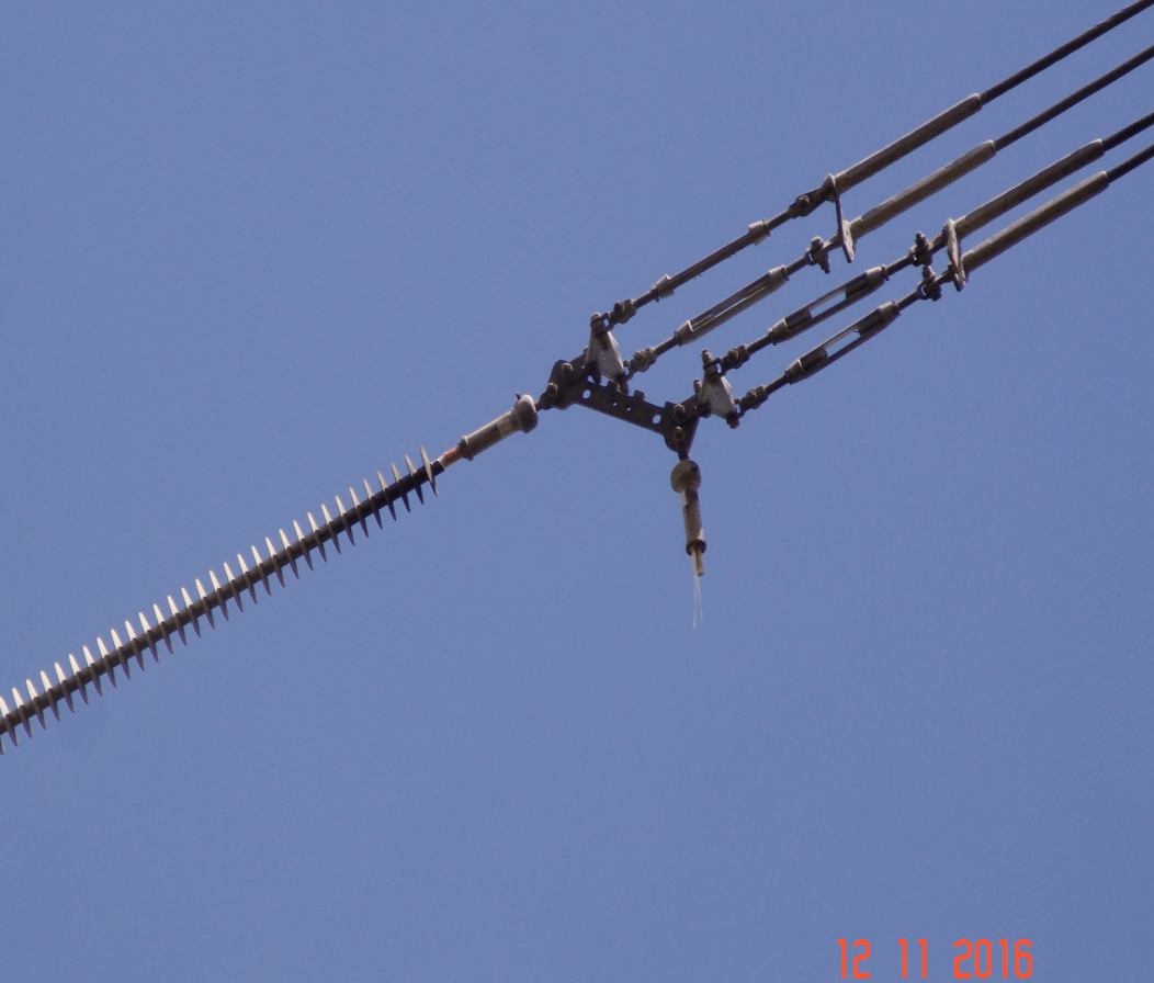
Tower No. 4 is a special tower where the inversion or rotation of phase A and C is carried out to obtain the correct phase sequence for its entry into the arrival Substation. The following figure shows the arrangement and scheme by which phases are rotated.
To assess cause of the failure, a photo record of the status of each insulator was made:
1. It was determined that all the insulators installed in Tower No. 4 had corona rings installed at both energized end and at tower end, except for the arrangement of double insulators that electrically separates phases A and C;
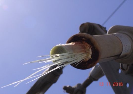
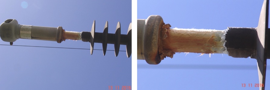
2. The insulator next to the one that had failed was in a critical state, with considerable loss of its polymeric cover as well as serious damage to the initial part of the fiberglass rod and pitting on the surface of hardware. Nevertheless, this insulator managed to withstand the mechanical tension of the conductors, calculated at 5.2 tons.
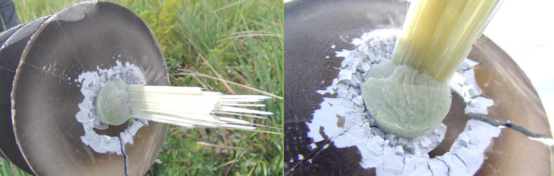
3. The insulator that had failed by brittle fracture was carefully disassembled and transferred to a laboratory where a scanning electron microscopy test could be performed. Several detached skirts were found on the ground.
• In both cases of failures since 2015, the polymeric insulators were manufactured by reputable suppliers in Germany and the United States.
• In the case of the failed insulator on the Caruachi – Macagua Transmission Line, there were several questions to find the technical explanation, e.g. the insulator located next to the fault was exposed to the same conditions of electric field and corona effects yet did not experience brittle fracture even though it had to endure the same mechanical moment when the other insulator failed and also supported the mechanical load of four conductors. Also, why did the damage to the polymeric cover of insulators fixed at the end of phase C not occur in phase A?
Conclusions
1. With this case, it is shown that, in the case of 400 kV transmission lines, it is extremely important that polymeric insulators have corona rings installed at the energized end – whether these are in suspension or dead-end towers. This is due to reduced life expectancy of a period not exceeding 14 years, from damage caused by corona in the area surrounding the terminal fittings. High electric field results in release of nitric acid that progressively destroys the silicone rubber until the fiberglass core rod becomes exposed to the environment. This then allows entry of water with either a ‘flashunder’ or brittle fracture failure. It is important to note that the fault that occurred in this particular insulator was not due to a manufacturing defect but rather caused by absence of the corona ring, which was not installed during the line’s construction stage.
2. It is recommended to apply UV corona inspection technology in the maintenance policies of public utilities. This condition-based monitoring tool represents a powerful means to detect advanced root cause failures. It also allows active monitoring the condition of components both on transmission lines and in high and extra high voltage substations during normal service. Depending on number and length of lines being operated, it is vital to establish an annual inspection frequency, at the least.
3. It is recommended that when power companies select polymeric insulators for new line projects, they include among their construction specifications, installation of corona rings, designed and supplied by the insulator manufacturer. This is to standardize and regulate electric field at the energized end and avoid exposing insulators to a phenomenon not visible or detectable by simple visual inspection. It is also recommended that, during the assembly stage, the Construction Inspector verify installation of each and every corona ring and that a line is not energized until installation of all these elements has been completed.
4. Another recommendation is that power companies include in their specifications for polymeric insulators a Vibration Test for sets of fittings, insulators and corona rings. This would be both for suspension and dead-end tower arrangements on all lines with average span length greater than 300 m and especially if there are two or more conductors per phase. This is to ensure that corona rings are not loosened as a result of conductor vibration or because they have not been properly installed.
[inline_ad_block]