Not long ago, the concept of ‘aesthetic’ and ‘compact’ overhead lines were not part of the lexicon at most power utilities and few realized their potential. Instead, traditional designs almost always prevailed when it came to new transmission line projects. It was not until recently that an ‘awakening’ occurred, driven by technology as well as a changed marketplace. Customers, interveners and the public in general all started demanding new solutions when it comes to the scale and appearance of power line structures.
This edited past contribution to INMR by Dimitri Georgopoulos, a Specialist in Transmission Line Specialist and consultant in Alberta, Canada reviewed insights and experience gained over more than two decades evaluating and implementing compact transmission line designs at a major local utility.

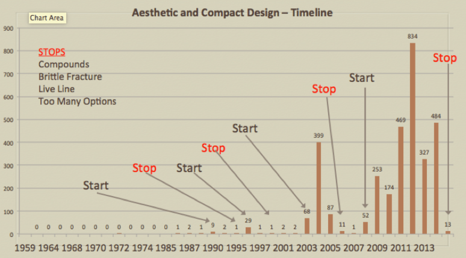
The ‘implementation of innovation’ concept is best depicted in the classic chart shown in Fig. 1. As evident, innovations are not easily accepted at first – a fact that also applies to most electricity supply utilities. In this industry, it is usually easier to ‘sell’ a new idea internally only after it has already become common practice elsewhere.
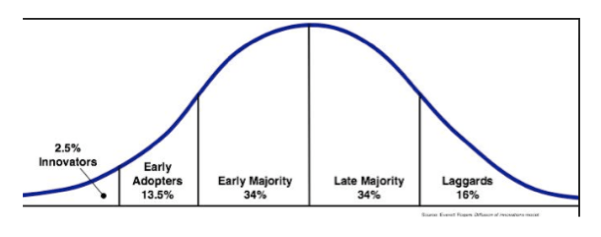
Moreover, utilities themselves are typically not innovators due to a variety of factors, including lack of specialized individuals within their ranks and, on a larger scale, lack of R&D departments charged with this task. Progress in structural or electrical innovation is therefore influenced mainly by external sources such as technical organizations, peer interaction conferences and manufacturers who propose new products and ideas.
Experience in Alberta
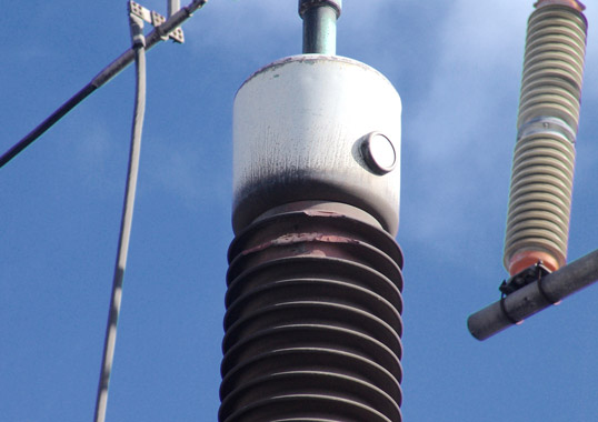
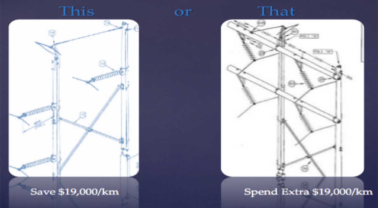
A major utility in Alberta began a process toward implementing compact line designs about 30 years ago, stimulated largely by a past INMR WORLD CONGRESS attended by one of its Sr. Transmission Specialists. A program to develop a family of new compact structures soon followed. Unfortunately, the process encountered a series of ‘stops’ and ‘starts’, largely due to uncertainties about composite insulator technology and reports of brittle fracture, reduced service life and possible incompatibility with live-line work (see Fig. 3).
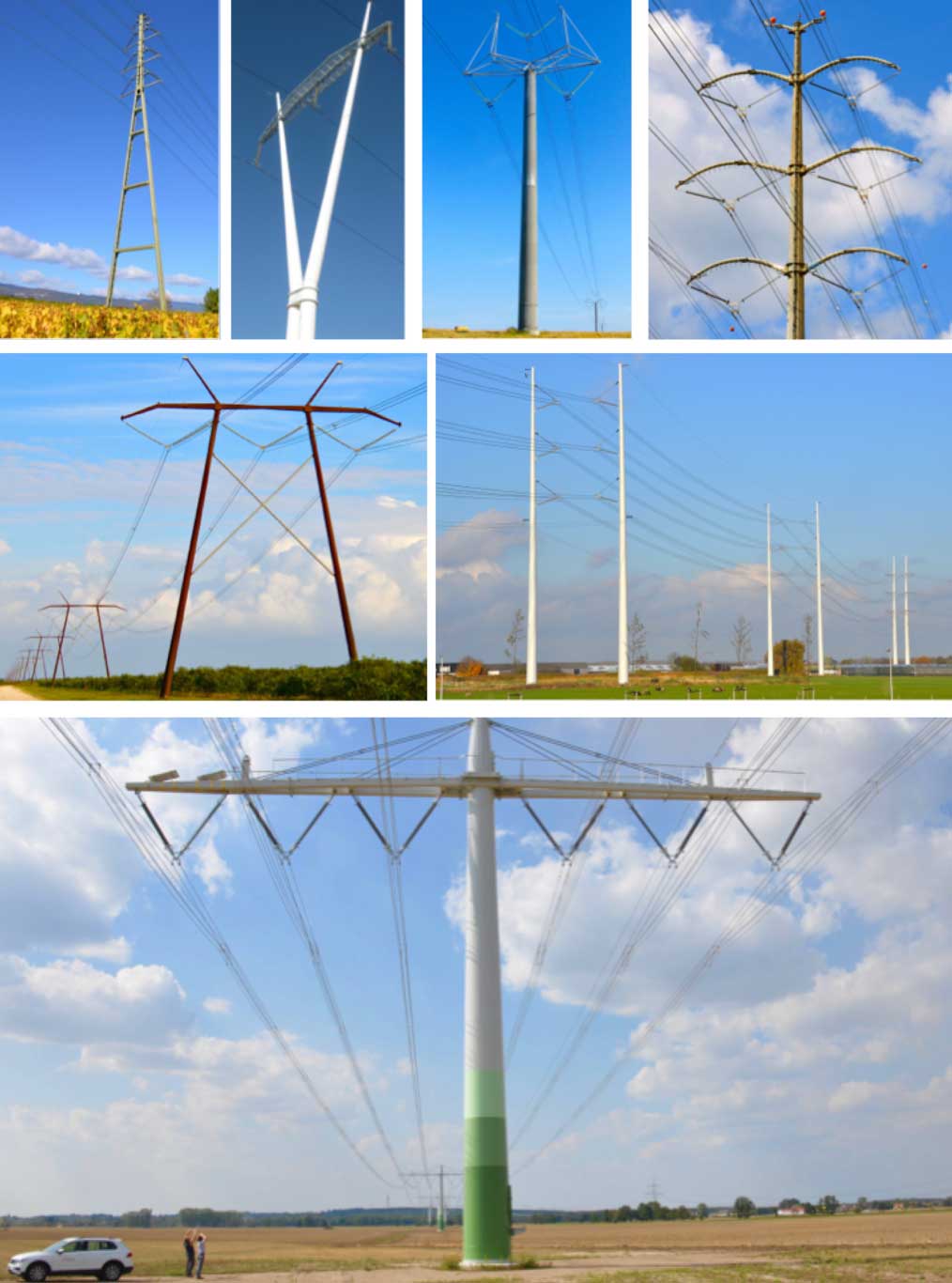
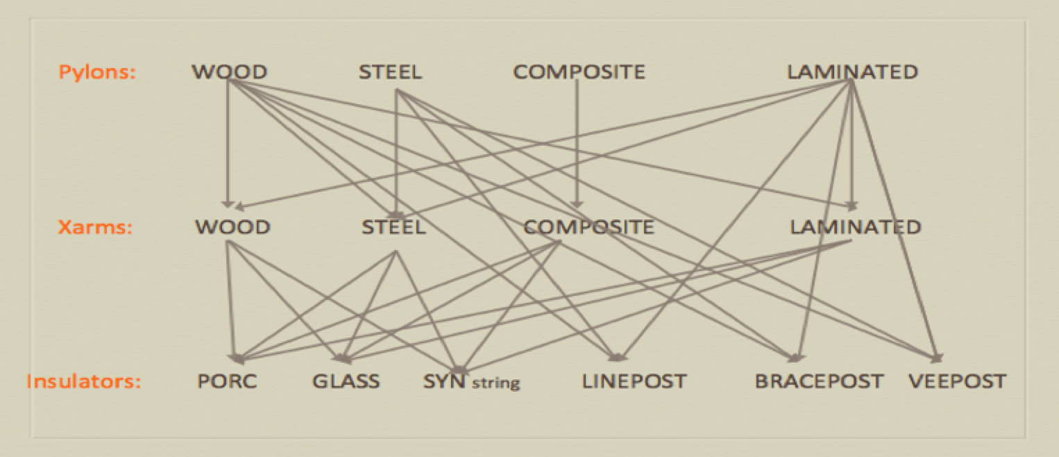
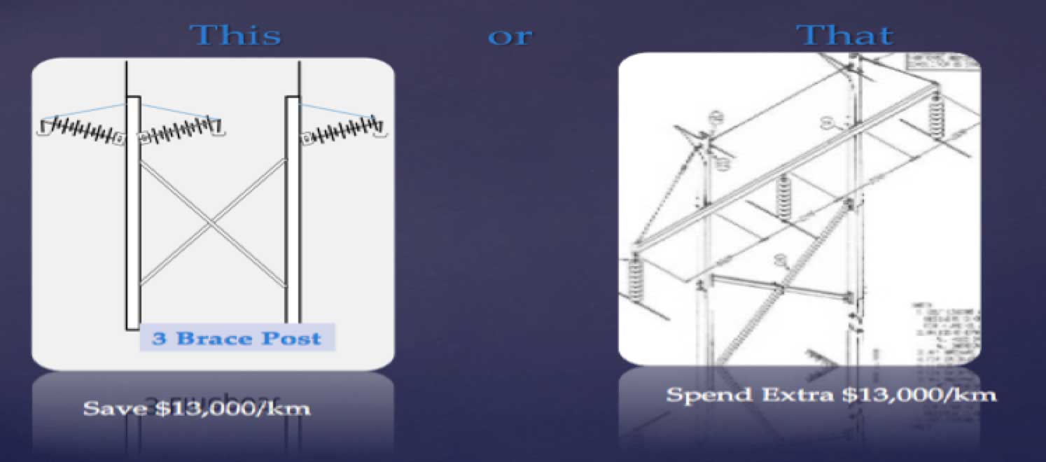
Engineers soon realized that they had to move away from a purely ‘menu’ approach to selecting new structures (as in Fig. 4) and more toward a ‘prescriptive’ approach, i.e. ‘good/better/best, based instead on holistic analysis. The goal was to create an easily understood rating system for designers and then proving that this rating system applied in at least 95% of all cases.
This required verifying which components and structure designs were most efficient in terms of factors such as: safety, reliability, constructability, cost, environmental impact, right-of-way requirement, support from landowners and customers, O&M efficiencies, procurement, warehousing and handling. All these aspects had to be analyzed by a team of specialists who also solicited input from stakeholders.

Safety
Safety of construction crews and the public is regarded as paramount and the key issue therefore became how to create ‘safer’ structures. Crews were surveyed and it was found that, to them, ‘safety’ meant simpler, lighter and modular-type designs. Existing structures were also reviewed with crews and it was found that compact designs were generally favored since these could reduce the material being handled by about half. At the same time, heavy components such as cross-arms as well as porcelain and glass insulator strings could effectively be replaced. Public safety was then also considered by reviewing reliability charts and how these could be improved. For example, at AltaLink, the category of ‘contamination’ is typically linked with risk of fires to poles and cross-arms. The best solution to eliminate such risk was a post design.
Reliability
As at most utilities, engineers consider reliability to be tied closely to service interruptions. Among North American utilities, two key metrics are used to gauge reliability:
SAIFI = System Average Interruption Frequency Index is commonly used as a reliability indicator and is the average number of interruptions that a customer would experience.
SAIDI = System Average Interruption Duration Index is another indicator of reliability and is the average outage duration for each customer served.
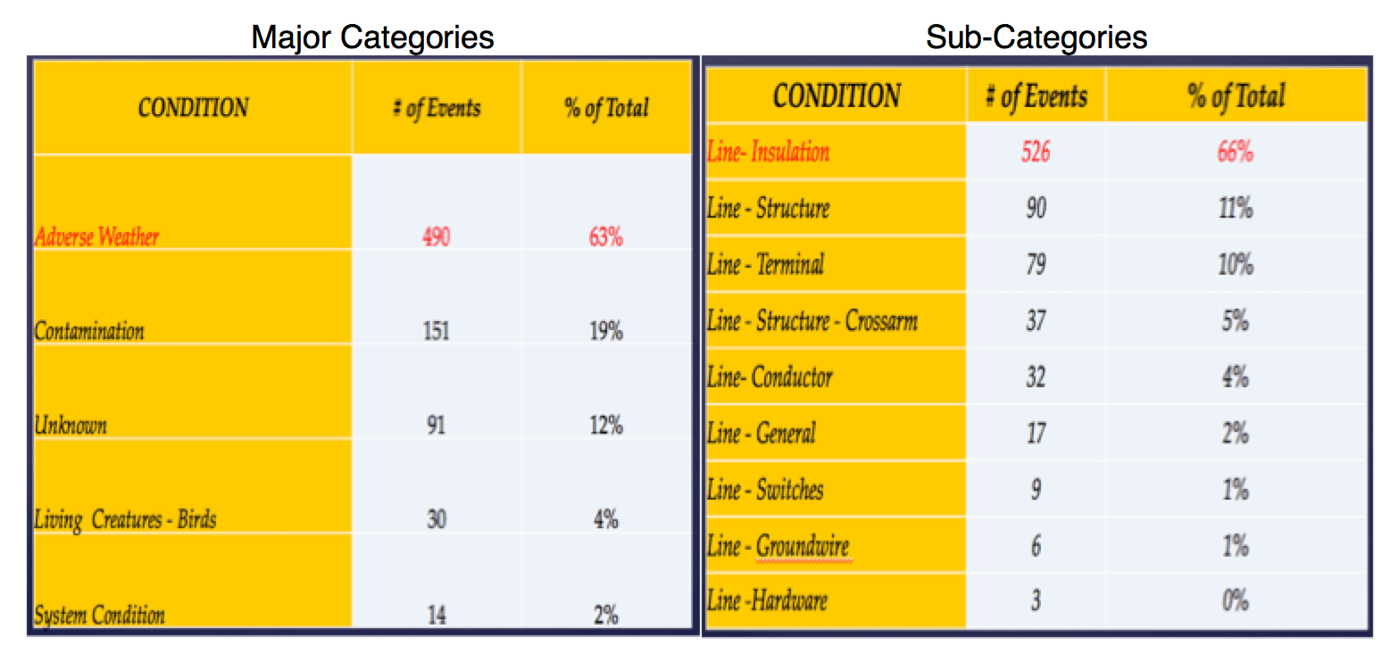
Fig. 5 provides a glimpse into major past causes of interruptions on AltaLink’s system. ‘Adverse Weather’, ‘Contamination’ and ‘Unknown Causes’ are the top threats to reliability. There is also a strong correlation to insulation. Composite type insulators, be it strings or posts, promise superior electrical characteristics and greater pollution resistance and should therefore help improve reliability by reducing or in some cases eliminating risk of cross-arm and pole fires. Decreasing duration of outages is one measure of success but elimination of the ‘possibility’ of such events is a better goal.
Constructability
Crews prefer lightweight modular designs that use the fewest and lightest possible pieces, thereby allowing them to build more structures each day.
Cost
• Construction labor is documented as the highest component in any new build and, based on publicly available records, usually falls between 53% and 63% of total transmission line project costs. As mentioned, the goal is to reduce crew time on a per structure basis, allowing building more structures to be completed in the same amount of time.
• Material cost, at about 27%, is documented as comprising the second highest share of total line build costs. Value engineering is used here to decide what is needed and to eliminate redundant components and materials. For example, is there really a need for pylons made of different materials or several cross-arm options or different insulator types? The objective is using less material and less costly material.

• Warehousing and handling are usually overlooked elements in total project cost. Typically, every structure option in a system will require spares and more options mean more stock and larger warehouses with more staff. AltaLink considers it more beneficial to stock items that are multi-functional rather than having many ‘one-offs’. This strategy would also help by:
· reducing number of standard structures;
· increasing procurement efficiency by reducing amount of ordering required;
· reducing warehouse and yard size due to less amount of material to be stored;
· reducing material handling by warehouse and yard staff;
· reducing material required to be managed and handled by crews in the field;
· reducing material to be returned to the warehouse.
• Right-of-way acquisition and maintenance costs carry into perpetuity and minimizing size of right-of-ways is essential. But there is also the non-monetary factor of relationship building. Actions and attitudes by a utility can foster good relationships with landowners that will last for generations.
• Environmental costs can be diverse, ranging from the obvious costs associated with pole and cross-arm fires to potential damage caused during construction and maintenance. Recently, pole and cross-arm suppliers indicated that wooden spar arms would soon no longer be available and this meant identifying the best replacement options.
• O&M costs are often overlooked when reviewing different design options and some designs carry a higher such component. Field staff usually state that their key request is ‘keep it simple and light’. For example, would crews prefer to replace a structure with line posts or use steel cross-arms with associated insulators, braces and other hardware?
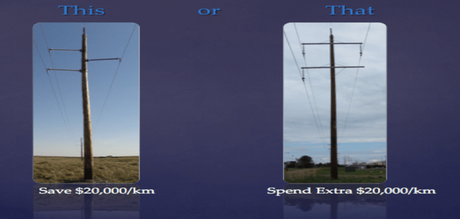
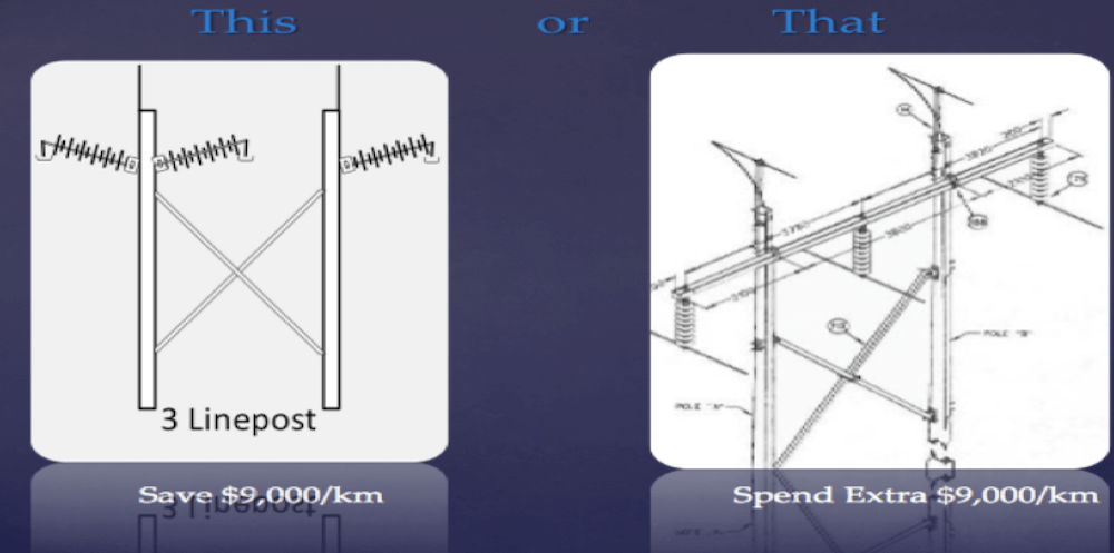
Internal analysis of the above factors concluded that, for new 138 kV construction, line post structures are ‘BEST’ and the most holistically efficient designs about 95% of the time. A brace post was termed ‘BETTER’ and the second most efficient design. This points to what the core of design should be and the importance of prioritizing options through value engineering. The following additional improvements were also confirmed:
• The existing menu of 29 standard structures can be reduced to only 16;
• Stored and emergency spares material can also be reduced;
• Right-of-way requirements decrease by from 10 to 50%;
• Amount of material used per structure is reduced by up to 50%;
• A single crew can assemble and erect an additional 3 structures per day (i.e. a 40% improvement);
• Need for insulator washing on preferred designs is eliminated;
• Risk of cross-arm fires are eliminated and incidence of pole fires reduced using the preferred designs;
• System interruptions are reduced.
A hierarchy of holistically efficient structures has also been confirmed.

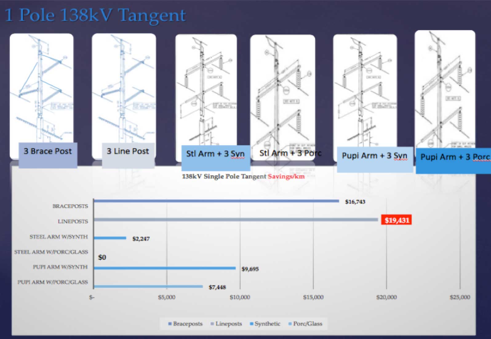
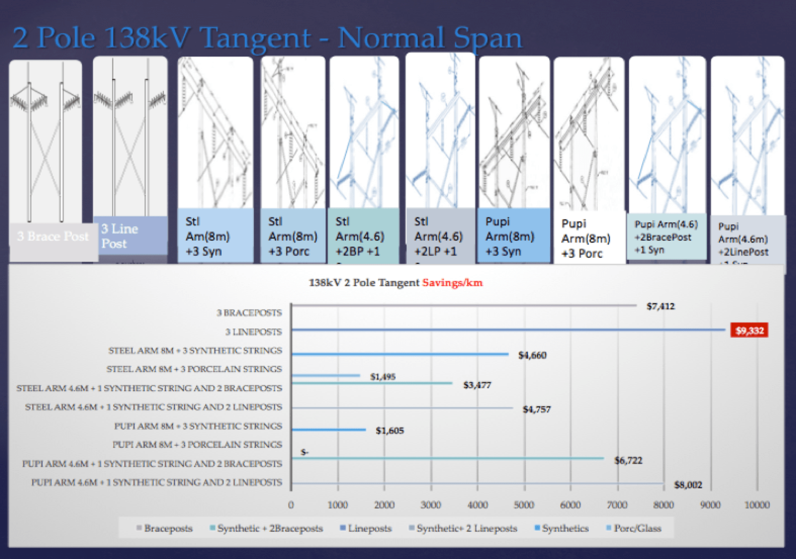
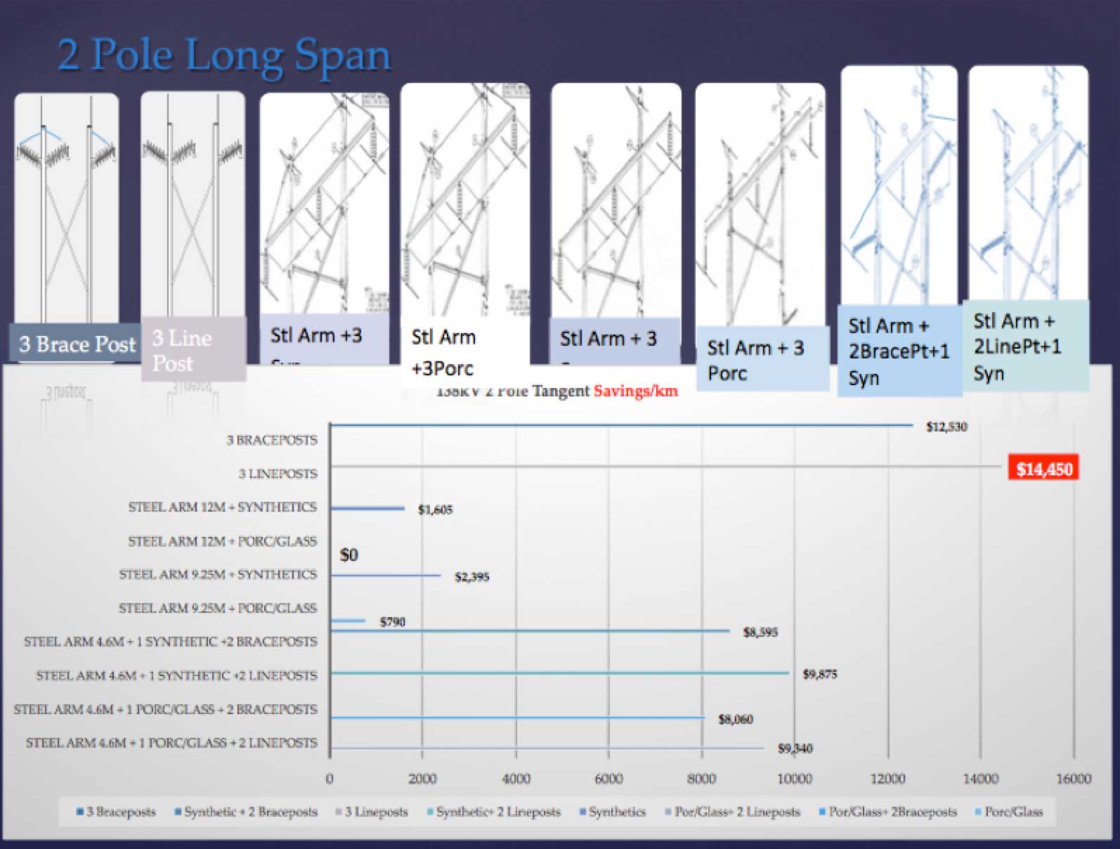
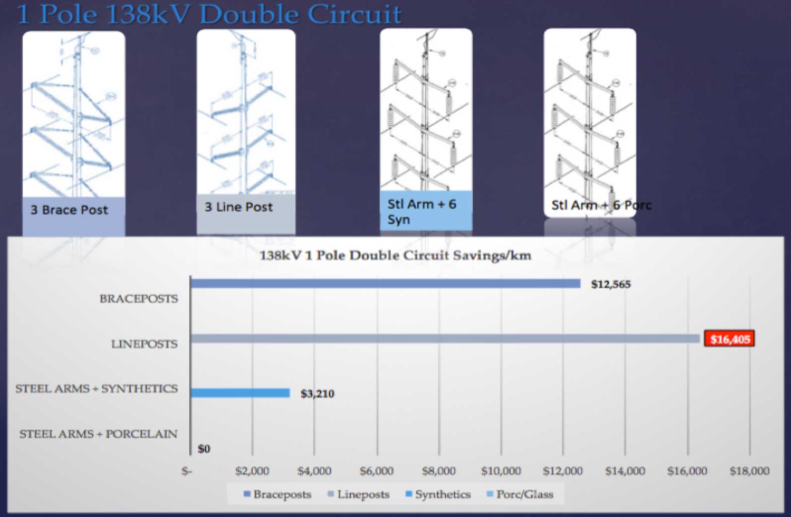
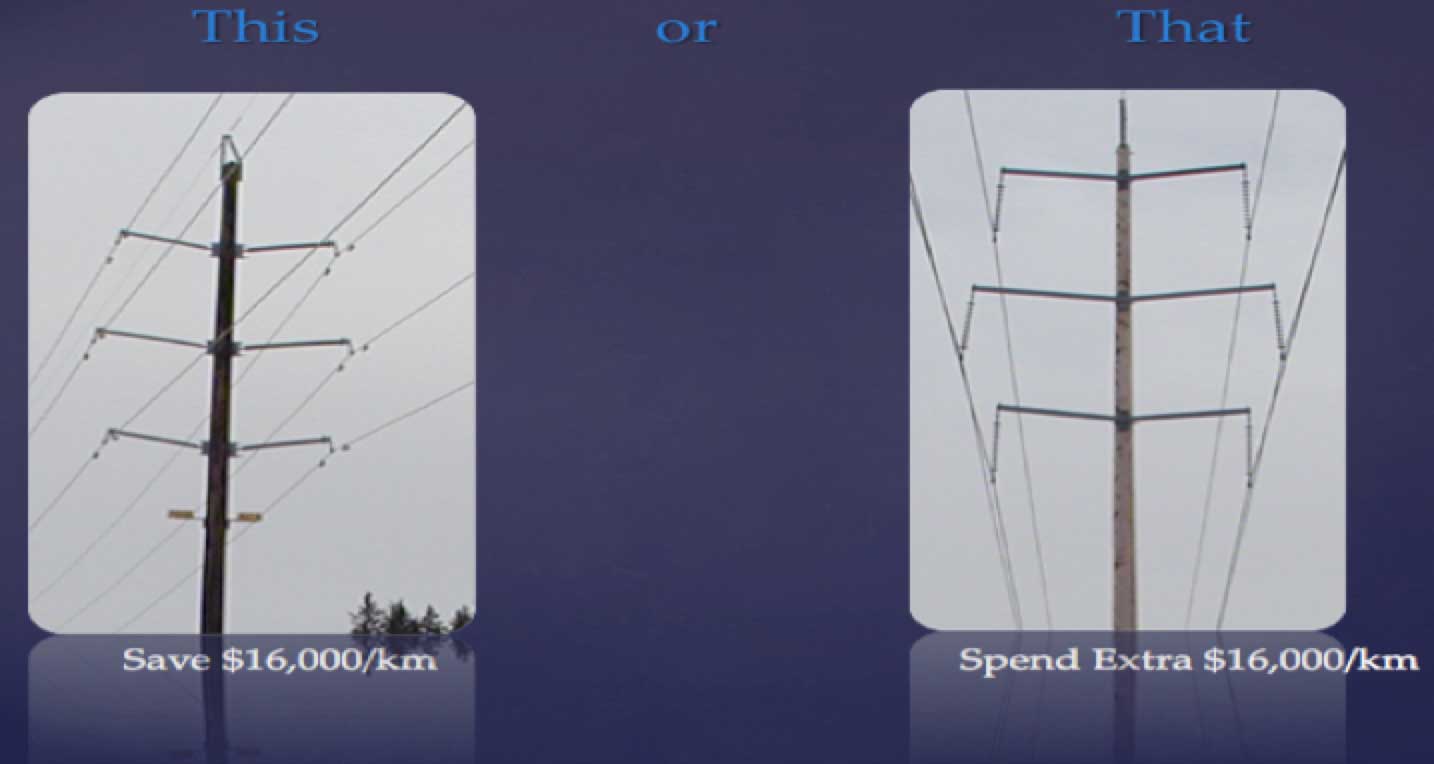
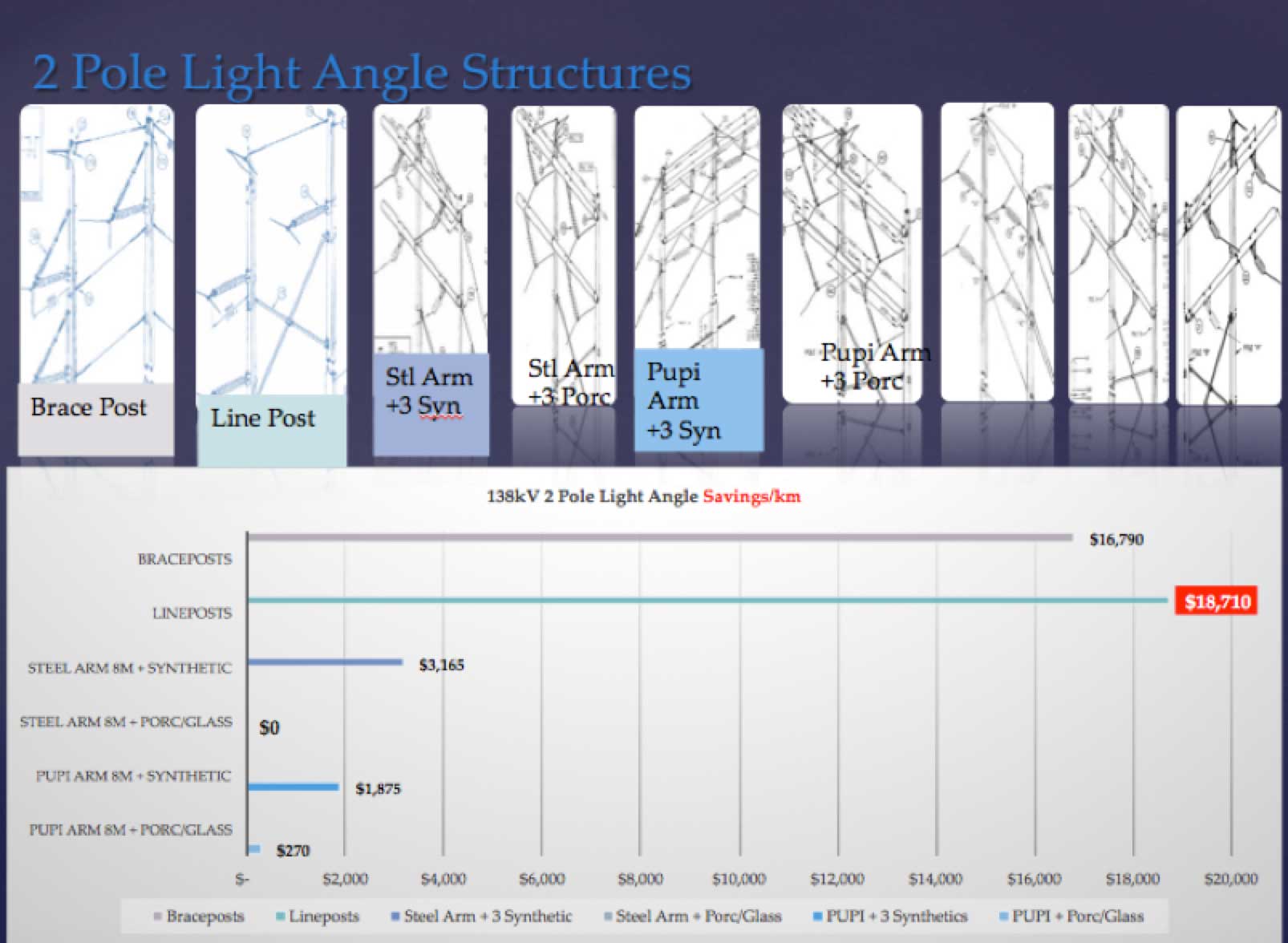
Analysis & Savings/km
Analysis of design options has shown the following savings, which are regarded as conservative:

[inline_ad_block]