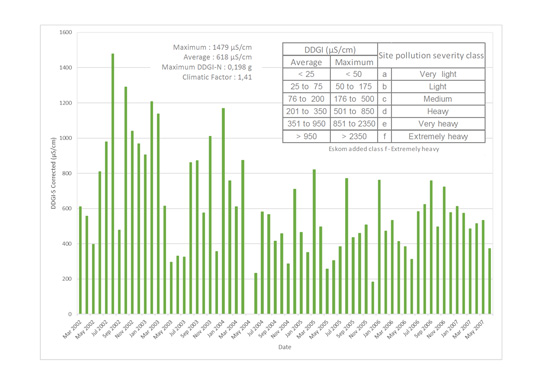
In heavily polluted areas of Oman or Eastern Saudi Arabia, operating experience has demonstrated that, even with 40 mm/kV creepage distance, ceramic fog type insulators do not offer satisfactory contamination performance and must be washed regularly to reduce contamination flashovers. While it is widely assumed that silicone insulators can operate at lower USCD values than either porcelain or glass, this has not always been found to be the case in such environments. Rather, there is concern that use of reduced leakage distance insulators in heavily contaminated areas may lead to a shorter service life. For example, one study of failures has suggested that leakage current during periods when hydrophobicity is temporarily lost (e.g. during dawn when damp pollution is present) can accelerate ageing and even trigger failure. It should also be emphasized that, when it comes to polymeric insulation, performance is not simply a function of the base polymer but also depends on several other factors. Fillers, for example, play a key role in tracking and erosion resistance. This edited past contribution to INMR by British expert, Brian Wareing, reviewed findings of investigations he conducted over many years into poorly performing insulation in demanding desert environments.
[inline_ad_1]
Alternative Polymeric Insulator Materials for Desert Environments
Silicone Rubber
UV can damage polymers by breaking the C-C bond that forms their molecular backbone. At lower wavelengths of 300 nm, the energy released by solar radiation is around 398 kJ/mole while the energy needed to rupture the bond is 348 kJ/mole at normal ambient temperatures. This explains why many polymers require the addition of UV inhibitors to ensure long-term stability. The Si-O backbone bond in silicone rubber, by contrast, requires 445 kJ/mole to be broken and is the chief reason silicone inherently performs better under UV exposure than do most other polymers. Still, there are other bonds in silicone polymers that can suffer UV damage, so it is not totally exempt from degradation. In desert areas, where temperatures can even exceed 50°C, for example, silicones can suffer some degradation, leaving behind a residue of conductive carbon that reduces tracking resistance. The low surface energy of polymers, compared with porcelain, is one reason why these materials retain hydrophobic properties. Silicone has about half the surface energy of materials such as EPR, EPDM and epoxy and this explains its superior hydrophobicity. This property, however, can be adversely affected by prolonged exposure to moisture and explains why silicone performs often poorly during continuous salt fog tests. Silicone rubber is best suited for environments that, while polluted, experience frequent rainfall since the material recovers its ‘as-new’ properties quickly after a pollution incident. This process occurs by re-orientation of the polymer chain and by migration of material from the bulk polymer to the surface by natural diffusion. However, lack of rain, as in the desert, makes performance of silicone uncertain.
[inline_ad_2]
Polyolefins
Many polymeric chains can become ‘chopped up’ by UV, especially where there is a defect in the chain due to improper manufacturing. Thermoplastic polyolefins such as polyethylene (PE), polyvinyl chloride (PVC) and ethylene vinyl acetate (EVA) that are free of defects can actually have an outdoor life of many years before they degrade. But such plastic materials must usually be stabilized with a mixture of UV screens for performance outdoors. Carbon black, for instance, is used in insulated overhead line conductor sheaths while antioxidants can slow down damage to the polymer chain due to pollution and electrical activity. Similarly, UV absorbers work by re-emitting energy from sunlight. Pure polyethylene has no absorption bands in the UV spectrum so, in principle, could last forever.
EPDM
Certain epoxy resins and the propylene part of EPDM rubber both have a well-deserved reputation of being vulnerable to UV. In the absence of information on specific formulation, a silicone would therefore always be a better choice, especially if exposure to high UV was the main decision criterion. This has been borne out by numerous examples of EPDM products suffering severe tracking in the deserts of Gulf countries such as Oman.
[inline_ad_3]
Bonding & Pole Fires
Polluted insulators allow tracking currents that travel between phases or to earth. With stay wires and in the absence of flashover, the existence of such currents is normally not a problem. However, lack of bonding of cross-arms or stay wires can result in the current over the insulators also tracking over the pole, leading to carbon tracks and eventually to the wood igniting.
Bonding to Cross-arms
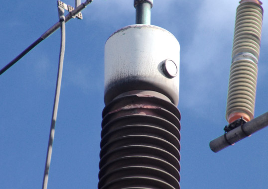
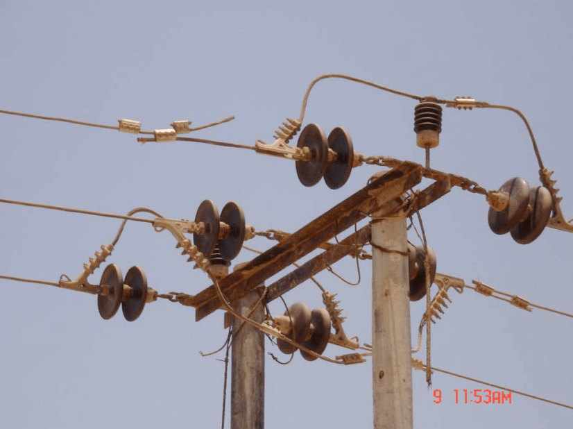
Fig. 1 shows a typical unearthed pole formerly used in the Omani desert network and where not all steelwork has been bonded. Here, a balancing stay wire has been bonded to the lower but not to the upper cross-arm. As a result, unbalanced leakage currents over the polluted porcelain insulators travel to the top cross-arm and from there move down the pole to the lower cross-arm and over the stay insulator to ground. These tracking currents over the pole section can cause ‘tree-like’ tracks, laying down carbon and giving future tracking currents a lower impedance path – thereby only increasing the risk. The insets in this photo show tracks from the pole bolt area of the top cross-arm down both sides of the pole. There is therefore a heightened risk of pole fires in this area. Fortunately, such tracks are easy to identify when line inspection personnel know what to look for and remedial measures can be taken pro-actively.
CLICK TO ENLARGE
Bonding all Steelwork
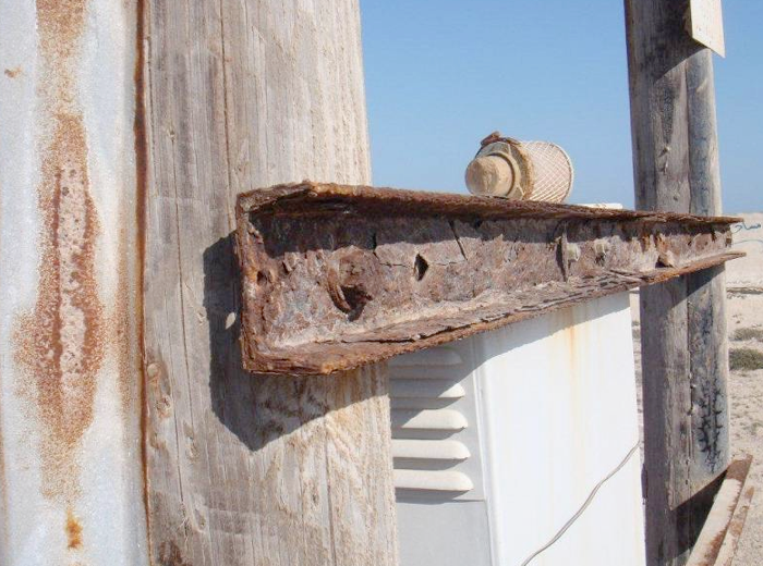
Fig. 2 shows an unearthed pole that has not had all the steel work bonded. As a result there is evidence of tracking from the upper cross-arm and also from the support cross-strut, that cannot be bonded as it is too close to the ground and could present a danger to personnel from floating voltages. In such cases, it is advisable that all steelwork be bonded and also earthed.
CLICK TO ENLARGE
Bonding to Stay Wires
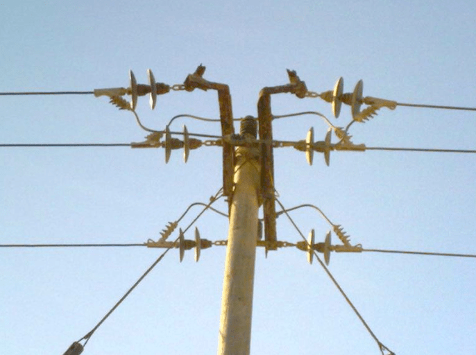
Fig. 3 shows a pole where there is no bonding between the stay wires on either the pole or the cross-arm. Unbalanced currents flowing over the insulators will raise the voltage of the electrically floating insulator. These currents then look for the easiest path to earth, down the bonded stay, across the stay insulator and into the ground. However, when bonding is not present, these currents must flow along the pole to reach the stay wire. Fig. 1 showed that, when there is a relatively long distance between electrically floating cross-arms, these currents spread out and ‘tree-like’ tracks appear. However, when the distance along the pole is short, as illustrated in Fig. 3, the tracking can be concentrated and deep. This increases risk of pole top fires but is easily resolved by bonding all steelwork.
CLICK TO ENLARGE
Importance of Insulator Quality & Specification
Problems due to poor or non-existent bonding all arise from application of insulators that are not appropriate for local service conditions. It can be difficult to detect poor bonding but the result of a combination of poorly performing polluted insulators and poor bonding is that pole tracking starts – the first step in pole fires.
[inline_ad_4]
Corrosion & Environmental Problems
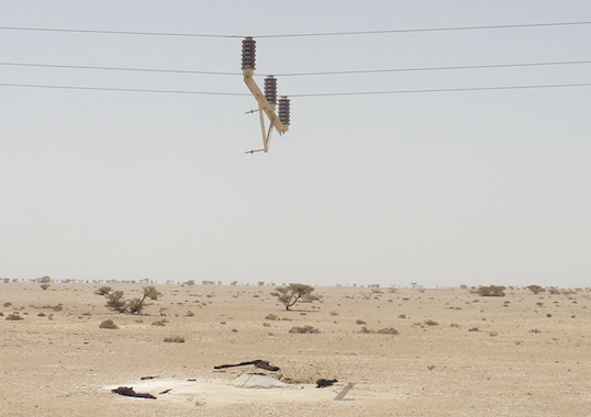
A further problem in the deserts of the Arabian Gulf and especially in the southeast of Oman has been corrosion of steel in cross-arms, transformers and conductors. This in turn has a direct bearing on insulator specification as it influences choice of materials for end fittings. Corrosion in this area is due to calcium salts from the desert and sodium salts from the Gulf in combination with high UV, high temperatures, NOx from corona discharges and SOx from vehicle diesel fumes. In many cases, the steel cores of ACSR conductors corrode away, leading to large conductor sags and the deaths of camels, goats and anything else that happens to pass nearby, including local residents.
CLICK TO ENLARGE
CLICK TO ENLARGE
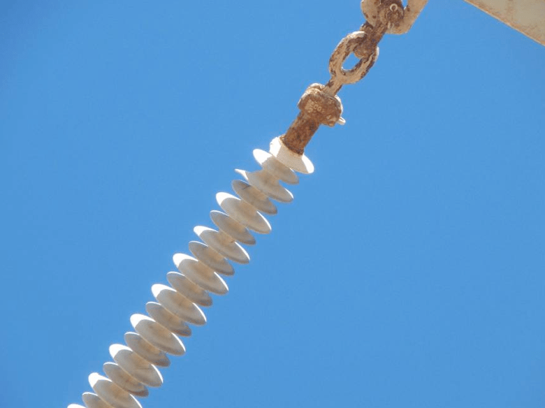
In such a corrosive environment, the galvanizing on fittings of polymeric insulators can easily be damaged, even with low levels of fault current at the contact points with connecting hardware. There will then be a reduction in their mechanical strength, with possible line drop and other safety hazards. Given this, most insulators at 132 kV in the area now incorporate a sacrificial ring for power arc protection. The arc initiation point, or roots, attach onto the ring thereby avoiding power being dissipated by the arc at the end fitting. However, some utilities do not install these devices correctly with the ring sometimes being fitted behind the insulator crimp, thereby leaving it exposed to damage.
CLICK TO ENLARGE
CLICK TO ENLARGE
The solution employed essentially removed all galvanized steel from the region’s medium voltage network. Steelwork on insulators is replaced with aluminium or stainless steel and cross-arms replaced by installed insulators directly mounted onto concrete poles. Indeed, concrete poles are now being widely used on medium voltage networks in Oman.
CLICK TO ENLARGE
CLICK TO ENLARGE
CLICK TO ENLARGE
Application of Spacers Between 33 kV Circuits
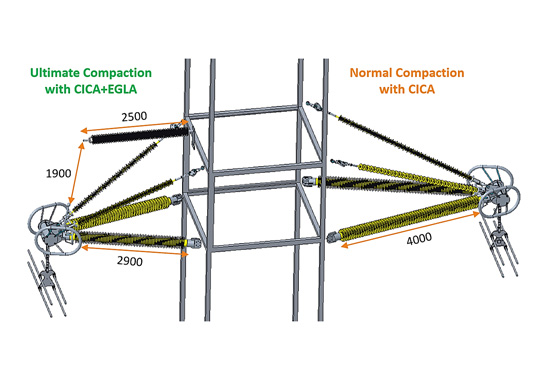
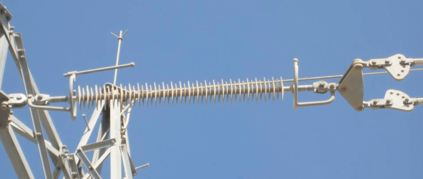
The Gulf States have a dense network of 33 kV lines to feed the region’s many oil wells. Sometimes these lines are less than a meter apart and, given frequent high desert winds, faults due to clashing have been a serious problem. To remedy this, a line contractor and insulator manufacturer co-operated in the past with another firm in applying live line techniques to install spacers between such lines, enabling the problem to be solved with no loss in oil production. The insulators used here were silicone type and met all specific creepage distance requirements for this service environment.
CLICK TO ENLARGE
CLICK TO ENLARGE
CLICK TO ENLARGE