Silicone rubber has long been applied as an insulation material for high voltage equipment due to being light and offering long-lasting hydrophobicity. However, its resistance to weathering is far weaker than for porcelain or glass. For example, while a porcelain or glass insulator is normally expected to have a lifespan of 40 or more years, a composite insulator might offer a shorter service life. This is even more the case for RTV silicone coatings.
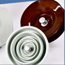
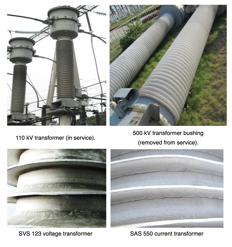
This edited past contribution to INMR by Prof. JIA Zhidong at the Graduate School at Shenzhen, Tsinghua University in China and LI Yaozhong, Sr. Engineer with the Xinjiang Electric Power Research Institute, described findings from research on how best to deal with ageing damage to two types of silicone materials commonly used for electrical insulation: liquid silicone rubber (LSR) and RTV coatings. LSR is typically a two part addition-curable material with low viscosity and good fluidity and used as housings of substation apparatus such as transformer and wall bushings, surge arresters and circuit breakers. RTV coatings are usually one part condensation-curable materials that are applied to porcelain and glass insulators to improve pollution flashover performance.

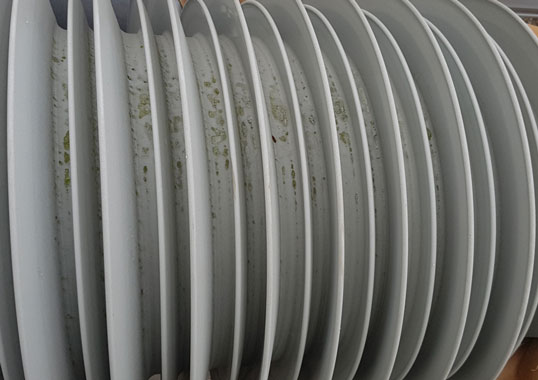
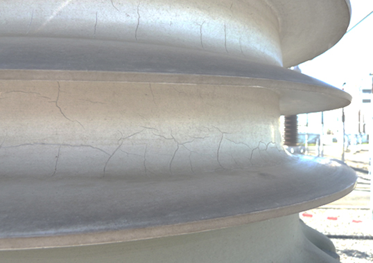
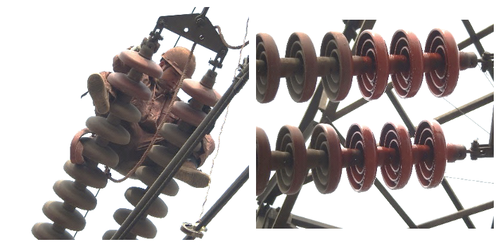
In recent years, the China Southern Power Grid has reported cases of severe ageing phenomena affecting both LSR hollow core composite insulators and RTV coatings. In Guangdong Province, for example, some hollow insulators experienced different levels of chalking and cracking that resulted in loss of hydrophobicity as well as decreased mechanical strength (see Fig. 1).
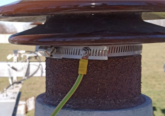
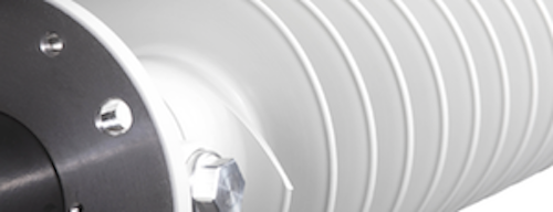
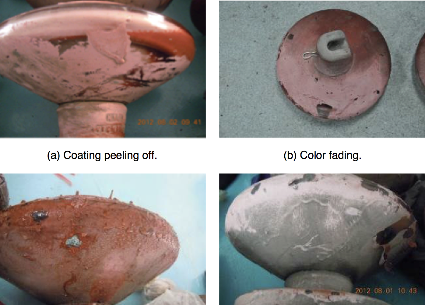
Reduction in mechanical properties is less important in the case of RTV coatings than for HTV silicone and LSR materials used in insulator housings. However critical ageing phenomena such as chalking, fading and peeling have also been observed on some RTV coated insulators after several years of service (see Fig. 2).
When such cases of ageing occur, common practice is to replace affected insulators with new ones. However, this course of action carries high cost, especially when it comes to wall bushings and other high voltage apparatus. At the same time, replacement can involve lengthy interruption times. For these reasons, repair and/or recoating are often better options.

Repairing Hollow Core Composite Insulators
Assessing Degree of Ageing
The first step when it comes to repairing a degraded hollow core composite insulator is to evaluate the extent of ageing and expected impact on performance. In this regard, in service insulators can be divided into three basic categories:
1. those not showing evidence of ageing;
2. those where ageing is deemed reparable; and
3. those where ageing has progressed to a point that they can no longer be repaired.
An optical microscope is used to study degree of ageing of a sample of the LSR housing. Fig. 3, for example, shows a typical magnified image of aged LSR sheds. A layered structure can be observed when dissecting the shed of this insulator such that the aged shed can be divided into 3 distinct layers. The surface of the shed is white and opaque and non-recoverable cracks are formed when bending the shed. This portion, with a thickness of from 0.3 to 0.5 mm, can be referred to as the ‘chalking layer’. Inside the chalking layer, the shed is relatively transparent with much lighter color than on the surface. This part is called the ‘transition layer’. Inside this layer is the core of the shed, referred to as the ‘non-chalking layer’, where all the normal properties of LSR are maintained.

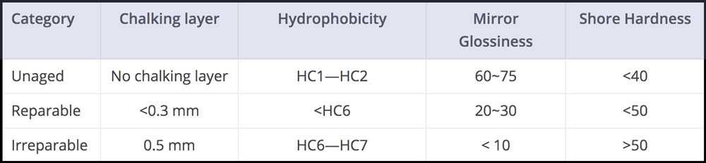
The cutaway view shown in Fig. 4 demonstrates that the ageing process develops ‘outside-in’ and therefore degree of ageing can be evaluated by measuring the thickness of the chalking layer. Further study has shown that degree of ageing of LSR sheds can also be determined by the following parameters:
1. Mirror Glossiness
The 60 degree mirror glossiness of unaged LSR is above 60 but gradually decreases with ageing.
2. Shore Hardness
Shore hardness of LSR increases with ageing such that the normal value of 35 to 40 becomes 45 or higher.
3. Hydrophobicity
The hydrophobicity of normal LSR sheds is HC1 or HC2 but for aged shed can drop to HC6 or HC7. Table 1 summarizes the parameters that can help identify whether or not an aged LSR housing can be repaired or is beyond repair.

Proposed Repair Technique
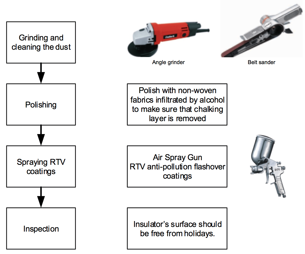
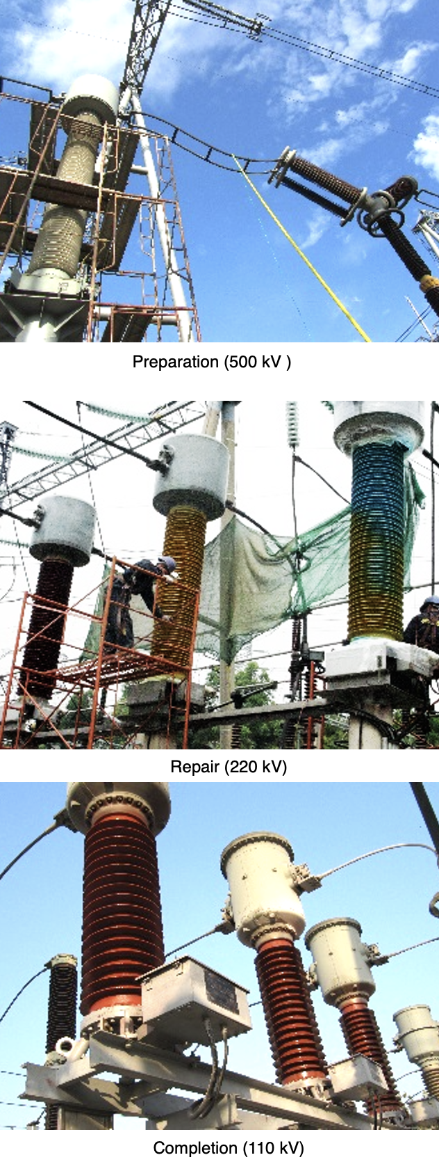
The top priority when repairing a hollow core composite insulator is recovery of its initial hydrophobicity while causing no damage to those portions where there is no evidence of ageing. Fig. 5 shows the steps in this procedure.
Several years ago, successful repair of aged hollow core composite insulators was carried out at three substations in Guangdong Province using the procedure described in Fig. 5.
Repairing Degraded RTV Coated Insulators
Recoating Weather
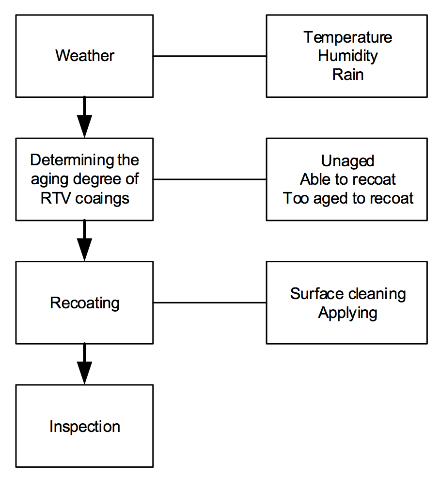
Adhesion and hydrophobicity are the two most important criteria to evaluate the condition of RTV coatings. Hydrophobicity is mainly determined by the silicone material itself while adhesion depends largely on application conditions and techniques. For example, when applied during bad weather or where there is dust or moisture on the insulator surface, even high quality RTV coatings may suffer poor adhesion during service. Fig. 7 proposes a recoating procedure of RTV coated insulators that show obvious signs of ageing such as loss of hydrophobicity or poor adhesion.
Adhesion
Circle scratch tests were conducted as part of this research in order to evaluate the adhesion of RTV coatings. Influence of temperature, humidity, surface condition (dust or moisture) were taken into account.
Temperature
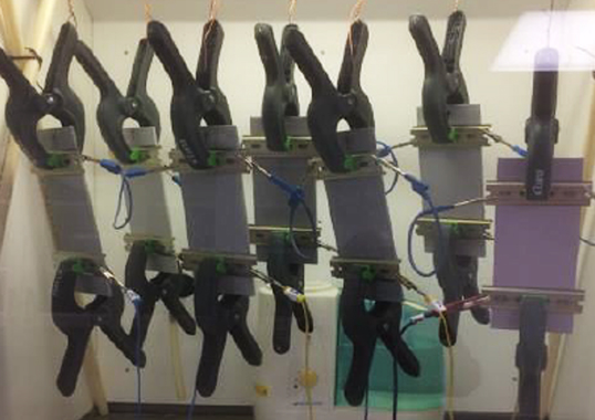
Temperature was set both at 5°C and 45°C, i.e. the lowest and highest temperatures that engineers might come across during recoating. Relative humidity (RH) was set as 60%. Circle scratch tests were conducted on samples, as shown in Fig. 8.
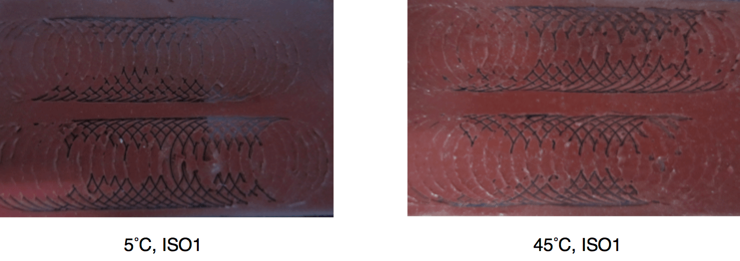
Test results showed that adhesion of both samples were ISO 1, deemed good for RTV coatings.
Humidity
Four tests were carried out under different humidity conditions. Temperature was set at 25°C and relative humidity was 10%, 33%, 75% and 100%. Fig. 9 shows the results.
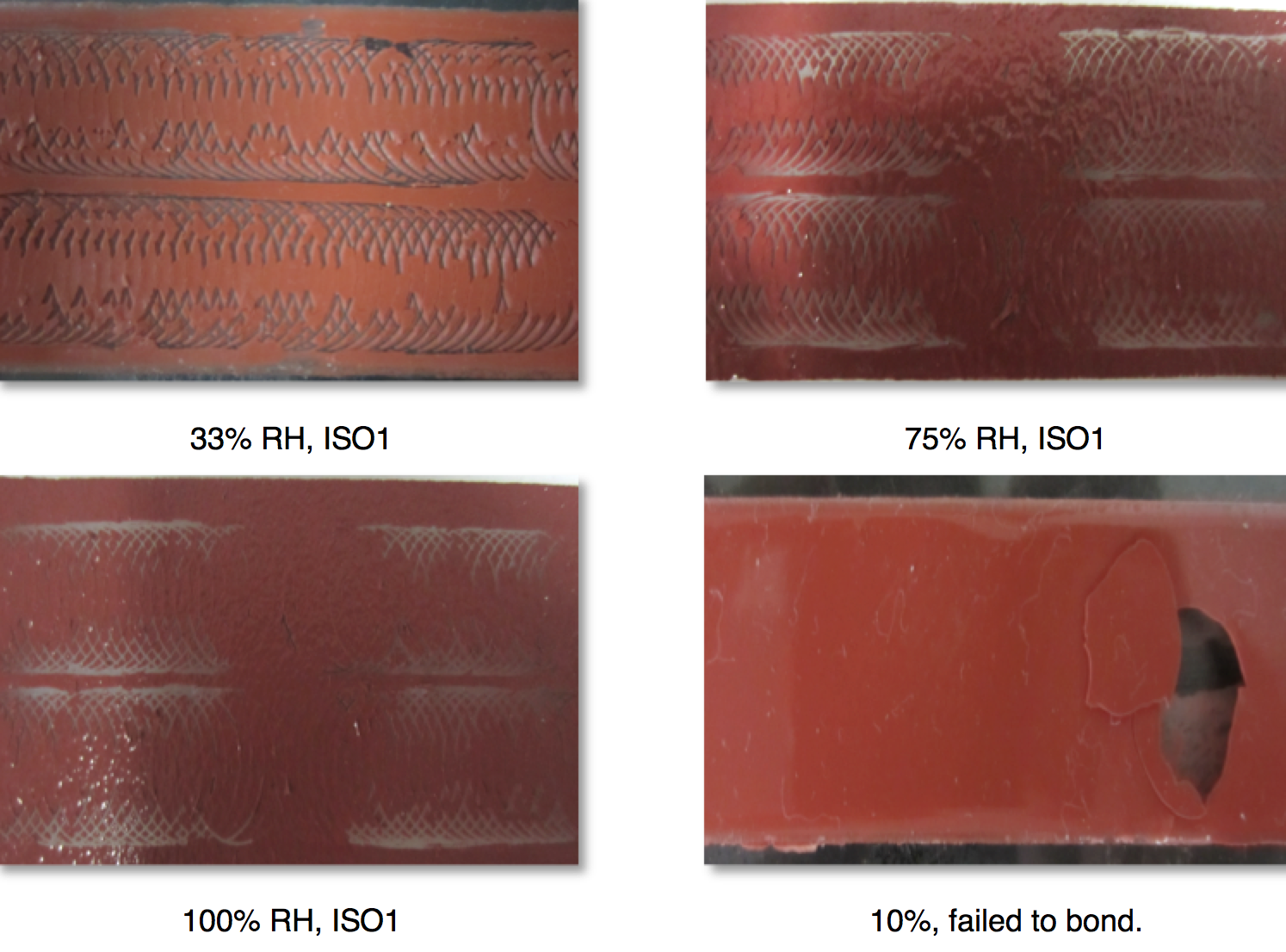
Adhesion of samples at RHs of 33%, 75% and 100% was ISO1 whereas for the sample applied at RH of 10% did not couple, which indicates that proper minimum humidity is important during vulcanization.
Surface Condition
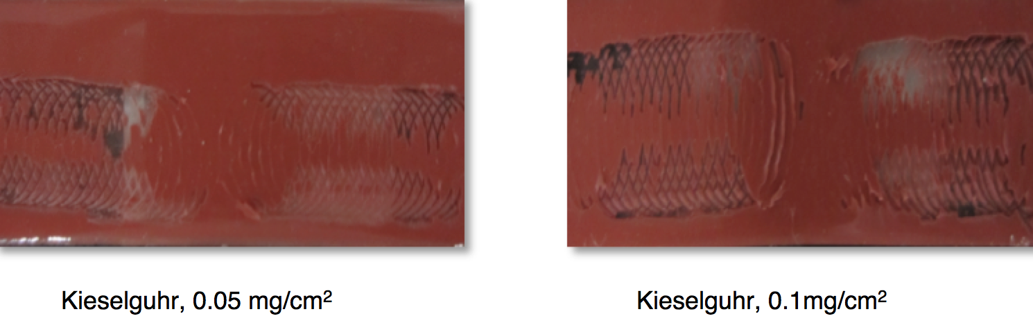
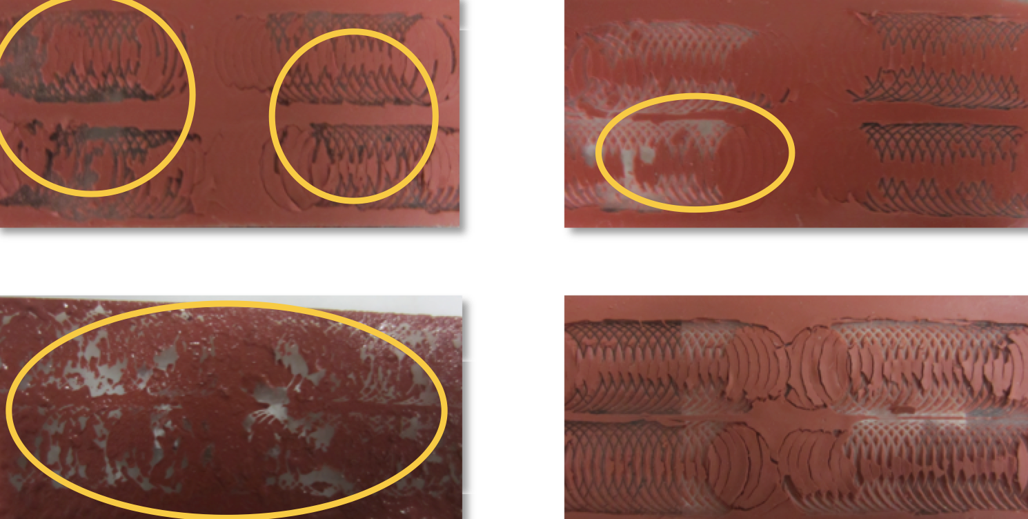
Surface condition of insulators has great impact on adhesion of RTV coatings. In re-coating practice, adhesion between the existing layer and the insulator surface is usually strong but it is of great importance to polish the surface from dust and moisture which, if present, will lower adhesion between the original coating and the new RTV coating (see Figs. 10 and 11).
For example, coating adhesion for both samples was lowered in the presence of dust. Testing was also conducted to assess the influence of moisture. In the four samples shown in Fig. 11, RTV coatings were sprayed and vulcanized with water droplets on the insulator surface. As with tests where there was dust on the surface, coating adhesion on all samples worsened.

Recoating Procedure
Spray Details
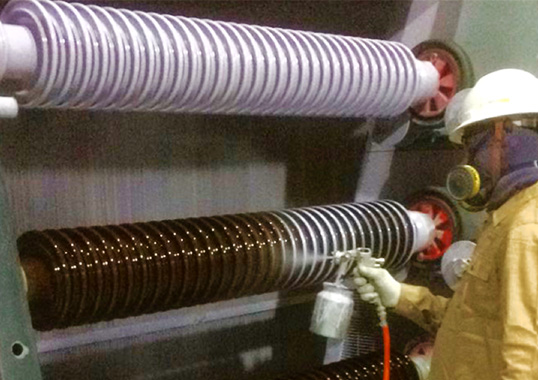
Spraying is recommended as the superior coating application method both in the IEEE standard and in the national standard of China. Yet details such as air pressure, distance between sprayer and surface and spraying time remain to be investigated. As part of this research, 6 different spraying conditions were simulated and spraying details and resulting appearance are shown in Table 2 and Fig. 12.
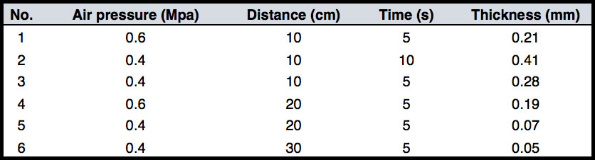
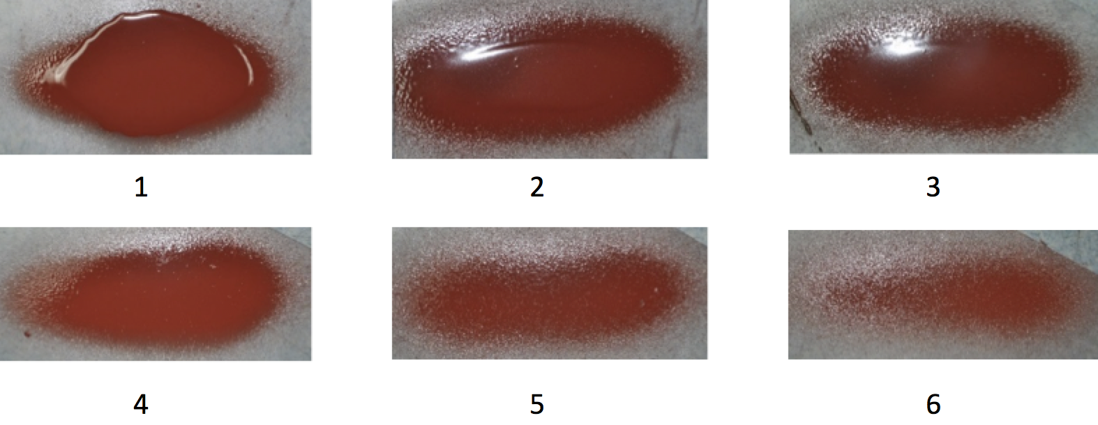
Those conditions linked to the spraying parameters for sample 4 proved most suitable to achieving optimum and even coating thickness. Successful re-coating of RTV coated insulators has already been carried out using these spraying parameters on 220 kV tension strings in Shanxi Province (see Fig. 13).
Summary & Conclusions
Ageing phenomena such as chalking and cracking of hollow core composite insulator housings made from LSR material can greatly impact outdoor performance. In the case of those housings deemed only ‘slightly aged’, repair is both time efficient and economical. Normal outdoor insulation performance can be regained by removing the chalking layer in the silicone rubber housing and spraying RTV coatings onto the aged surface. Mirror glossiness, Shore hardness and hydrophobicity are all parameters that can help evaluate extent of ageing of LSR housings and determine which insulators can be repaired and which have aged beyond repair.
To repair an aged insulator, the first step is to use a grinder to remove the chalking layer and then clean the surface with an air spray gun. The second is to treat the surface with an RTV silicone coating to improve the degraded hydrophobicity.
As far as RTV coated insulators are concerned, removing the original coating is inefficient and hence the better choice is to recoat new RTV coatings directly over the original layer. Weather, surface condition and application methods all influence adhesion between the new and the original coating. Tests have shown that adhesion of RTV coatings is best when applied at ambient temperatures from 5°C to 45°C. High relative humidity will not affect adhesion whereas extremely low humidity can lead to coupling failure. Dust and moisture have a great negative impact on adhesion and therefore must be thoroughly eliminated. Spraying is believed to be the best method to apply RTV coatings and ideal air pressure, spraying distance and time are 0.6 MPa, 20 cm and 5 s respectively.
Attend the 2023 INMR WORLD CONGRESS in Bangkok this November, where a range of experts will review experience with performance of coatings applied to electrical insulators.

[inline_ad_block]