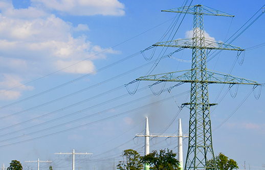
Integration of renewable energy sources into the electrical system in Germany has required adapting and expanding the existing grid. At the same time, public opposition to added infrastructure has meant that system operators face lengthy approval processes for new overhead lines. Although conventional designs have proven efficient and reliable, these typically have significant visual impact in terms of line corridors as well as tower dimensions and therefore encounter strongest resistance. As a result, there have been initiatives to develop compact overhead line designs – part of an overall trend seen across the globe. The expectation is that innovative design, combined with a communications plan validated by independent studies, will help address the challenge of promoting more rapid public acceptance.
Several years ago, 50Hertz Transmission, one of four major German TSOs, initiated an integrated approach to develop a compact overhead transmission line known as ‘compactLine’. This edited 2017 contribution to INMR by 50Hertz engineers reviewed the process as well as some of the unique features of this design.

Goals & Requirements
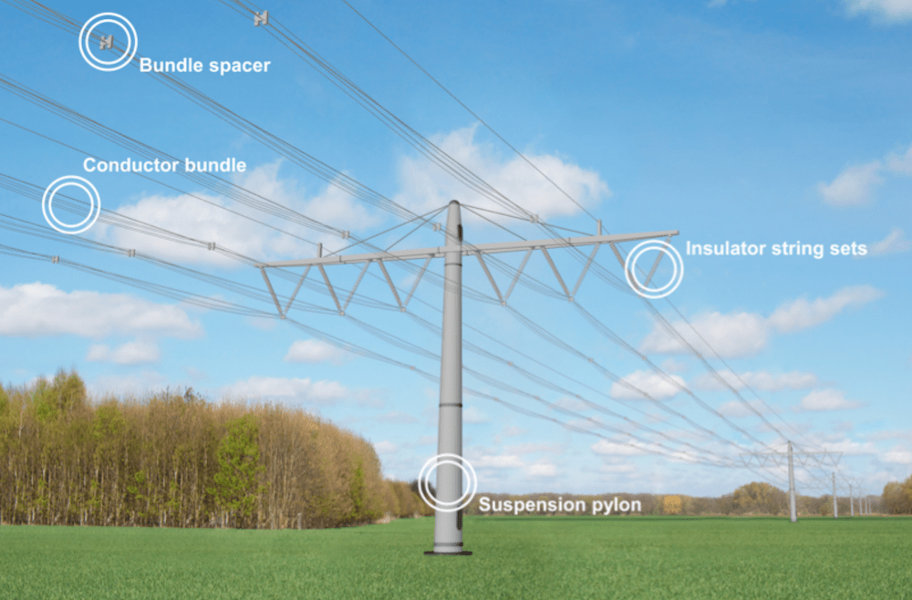
To allow any proposed new line concept to operate efficiently within the existing overhead transmission system, a set of technical requirements had to be fulfilled. Among these preconditions in the case of ‘compactLine’ was a double circuit 400 kV scheme of suspension and tension towers that could potentially replace existing conventional overhead lines. In terms of conductors, a quad bundle, i.e. 4 x ACSR 434-AL1/56- ST1A, with overall ampacity of 3600A and minimum ground clearance of 12.5 m was deemed essential. In regard to overall dimensions, corridor width could not exceed 60 m while maximum average tower height was limited to 40 m, given span lengths of up to 420 m. Another issue was to have as few additional constraints as possible compared to conventional lines when it comes to issues such as ice loading, maintenance, span length and materials used. While some of these criteria have been fulfilled by other compact line designs available today, none could cover the combination of all such requirements.
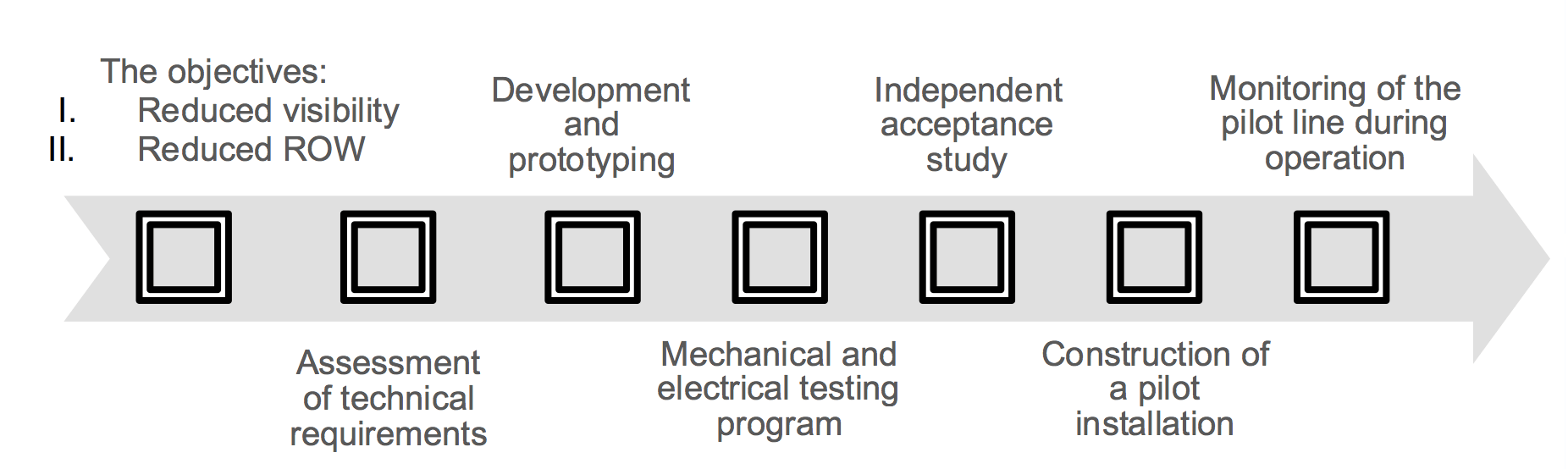
50Hertz therefore initiated a research project in 2013 with the aim of developing a completely new overhead line concept with significantly reduced height and width, leading to lower visibility as well as reduced right-of-way (ROW). These challenges had to be targeted at a technically feasible solution that met all requirements, making this a complex project requiring diverse skills and experience. Therefore, 50Hertz cooperated with strategic partners in component design and installation (i.e. Spie SAG) and then manufacturing (i.e. RIBE). Moreover, a testing and research institute (i.e. FGH) as well as a technical university (i.e. RWTH Aachen) were also part of the consortium, supported as well by an insulator manufacturer (i.e. Lapp Insulators) and the German Federal Institute for Material Research. The research project was co-funded by the German Federal Ministry for Economic Affairs and Energy. Fig. 1 shows the sequential development process through three working packages: a research phase (2014-2016); a construction phase (2017-2018); and a monitoring phase (2018-2019).

When developing any totally new technical solution, definition of objectives and requirements is crucial. System development and component prototyping as well as mechanical and electrical testing were therefore core elements during the engineering phase. These various activities were followed by an independent acceptance study to investigate how the newly developed design performed when it came to public acceptance. Construction of a pilot installation of the new line concept as well as in-depth monitoring during operation represented the final step in development.
CLICK TO ENLARGE
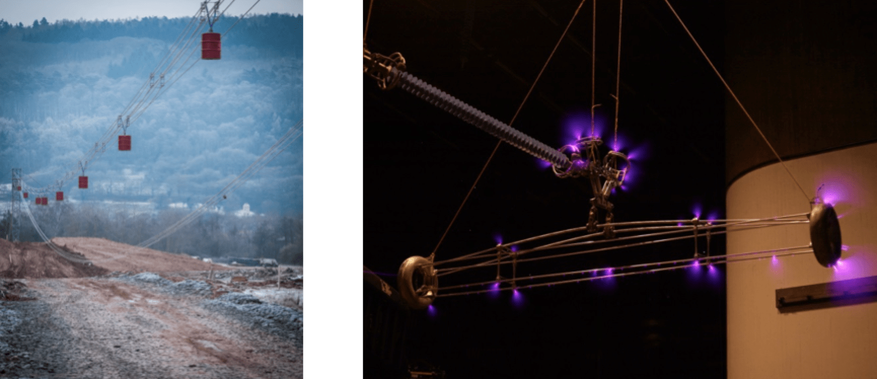
To meet all design requirements, the new overhead line concept had to be assessed differently than what was typically done in the past and new components had to be developed and simulated. These prototype components were then subjected to mechanical tests followed by further electrical testing of those versions that successfully passed the mechanical tests. In addition, full-scale tests at a 1.2 km long outdoor facility were needed to verify mechanical functionality of the conductor bundle system as well as insulators
Due to the novelty of the concept, no practical experience or simulation software was available to otherwise confirm these parameters. During these full-scale mechanical tests, the focus was on dynamic behaviour of the system as well as on the stationary mechanical strength of components. Other important aspects included electromagnetic field emission as well as audible noise from operation of the line. Extensive simulations were conducted to investigate these factors and to optimize geometry of conductor phases to ensure that the design would meet all regulatory requirements.
CLICK TO ENLARGE
Components
In order for the new overhead line concept to become technically feasible, all specially developed components also had to pass testing and simulation to verify operability. This goal was achieved by early 2017 and the full set of line components required was finalized. These include:
CLICK TO ENLARGE
Steel Support Rope & Phase Conductor Bundles
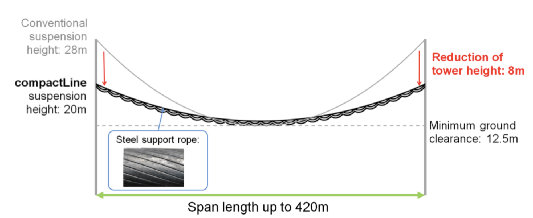
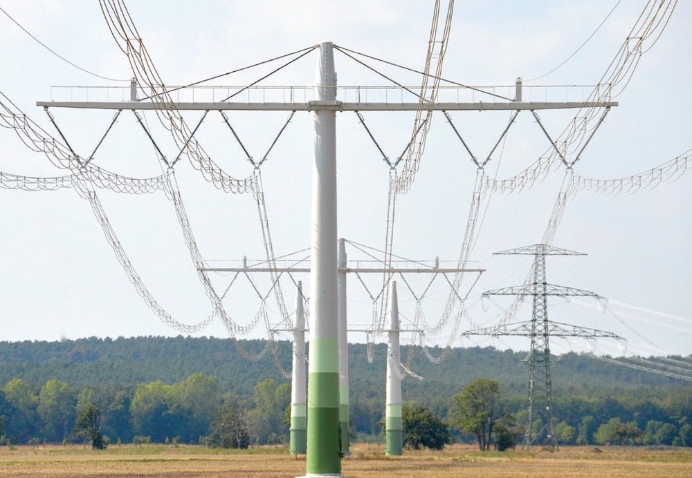
The principal technical characteristic of the new line concept is based on significantly reducing conductor sag without compromising required minimum ground clearance of 12.5 m. Indeed, reducing sag in each span was key to allowing much reduced tower heights and was achieved by using two steel support ropes added to every conductor bundle. While new to the area of overhead power lines, application of steel rope in cable cars as well as in bridges has long been used. The steel rope in this case has a 26 mm diameter and consists of stranded, hot-dip galvanized steel wire having an overall tensile strength rating of 791 kN. These ropes are installed under high tension, while phase conductors hang, like garlands, beneath. Resulting sag in each span, i.e. the catenary, is therefore no longer being defined by the conductors but rather by the steel ropes to which they are attached.
CLICK TO ENLARGE
CLICK TO ENLARGE
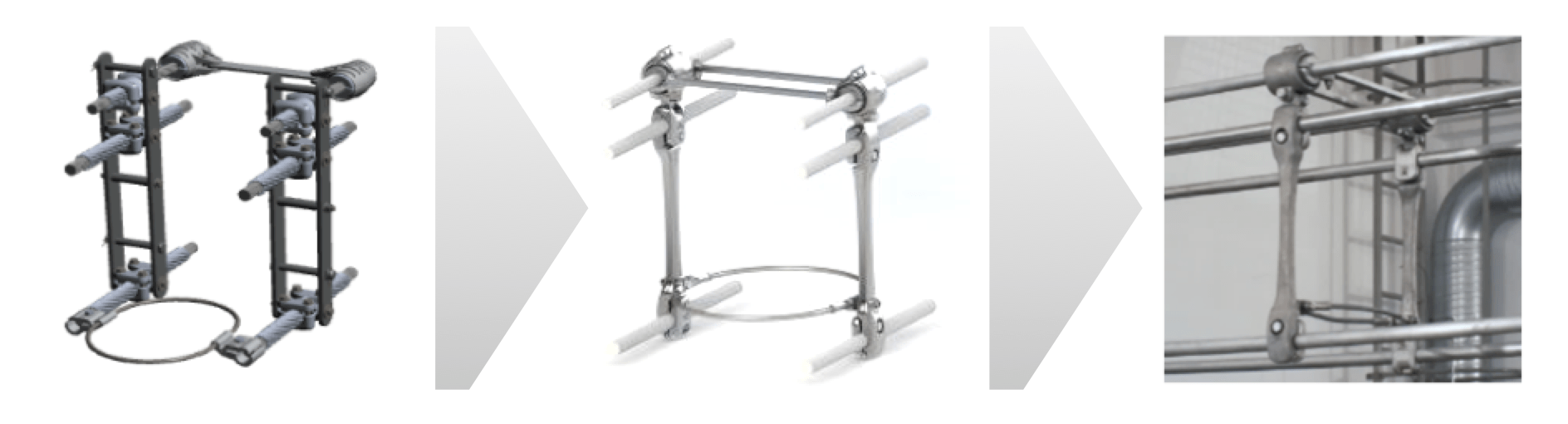
Bundle Spacer
Newly developed ‘spacers-conductor supports’ are installed at regular intervals and serve the dual task of spacer and also attachment point for the four conductors to the steel support ropes. Thus, while tension in the steel ropes is high, for the conductors themselves it can be comparatively low while still maintaining low sag between consecutive spacers. This conductor configuration, however, faced a series of technical challenges since this component not only needs to maintain the spacing between individual conductors but must also support their weight while allowing as much movement as possible. A series of different prototypes were developed with the version finally selected being a 400 mm x 500 mm squared unit made of cast aluminium.
CLICK TO ENLARGE
CLICK TO ENLARGE
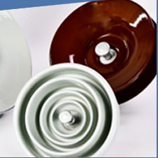
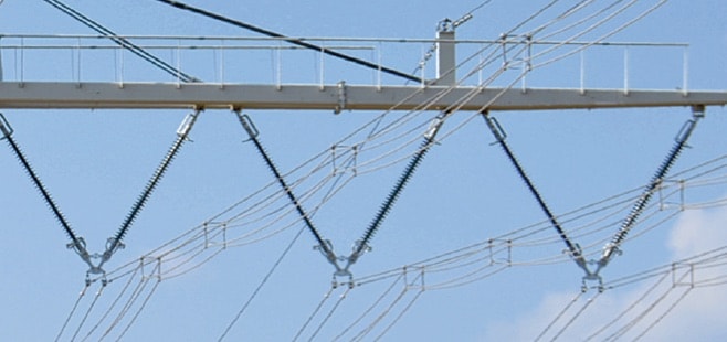
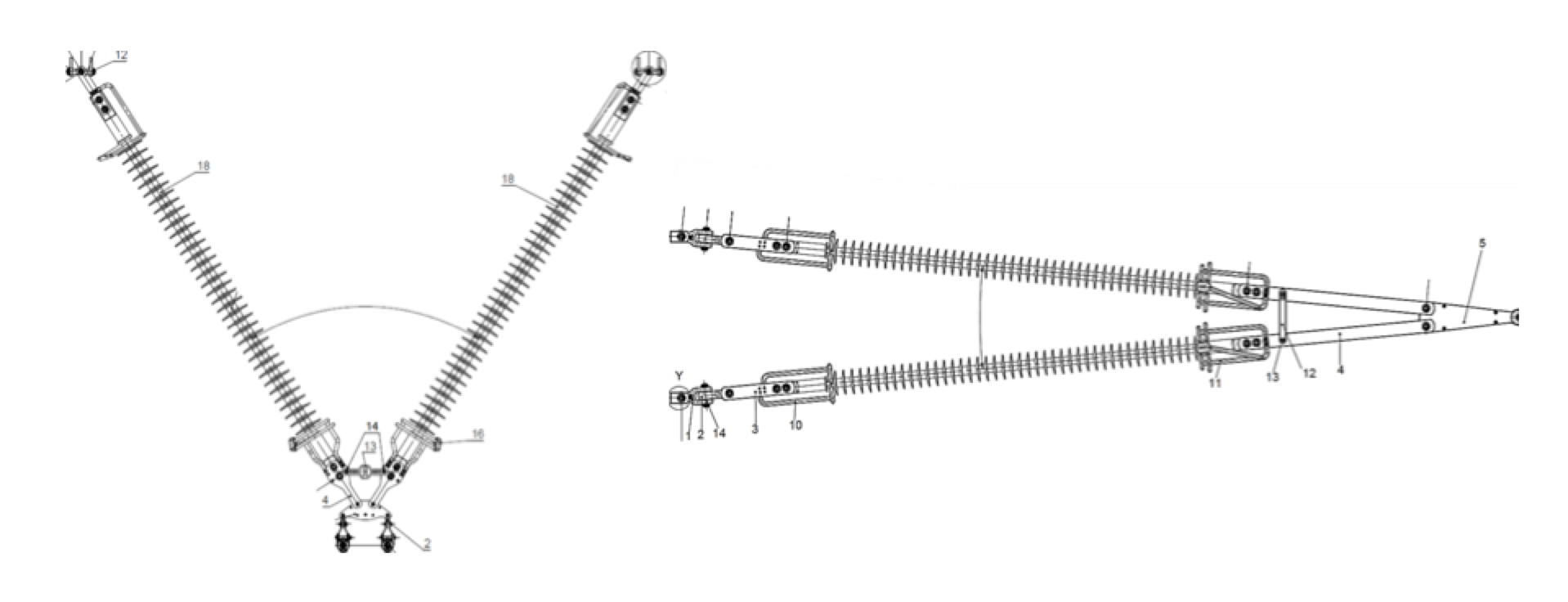
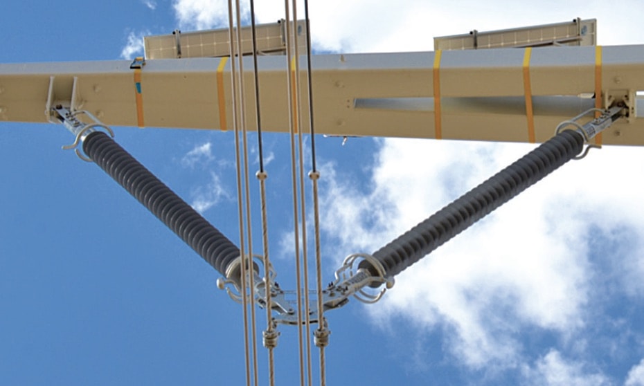
Insulator String Sets
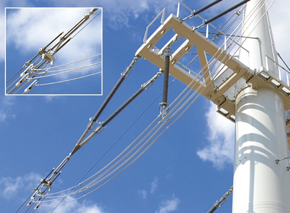
Special insulator string sets and fittings also had to be developed for both suspension and tension towers. The suspension string set is a comparatively wide ‘V’ configuration of composite insulators with 88 mm core diameter. The tension string set, by contrast, is a long, narrow ‘V’ configuration of composite insulators having 63 mm core diameter. Among the benefits of the steel support rope is reduced lateral movement of conductors due to wind. To take advantage of this benefit, a rigid ‘V’ string arrangement was selected for suspension insulators to withstand increased compression and tensile forces. Tension insulator sets must be able to handle the high tensile forces from the steel support ropes. Taking these relevant load factors into account, insulators were designed for tensile forces up to 1320 kN.
CLICK TO ENLARGE
CLICK TO ENLARGE
CLICK TO ENLARGE
Suspension & Tension Towers
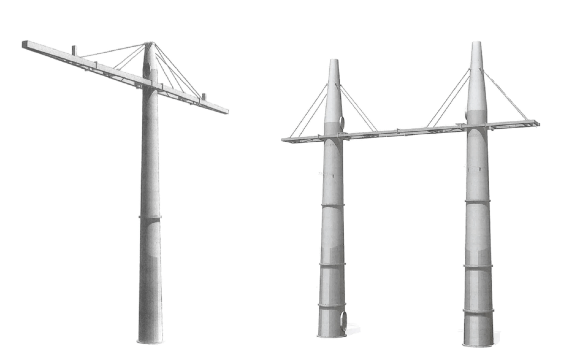
The additional weight of the high-tension steel ropes and resulting significantly higher mechanical forces required complete re-design of both suspension and tension towers.
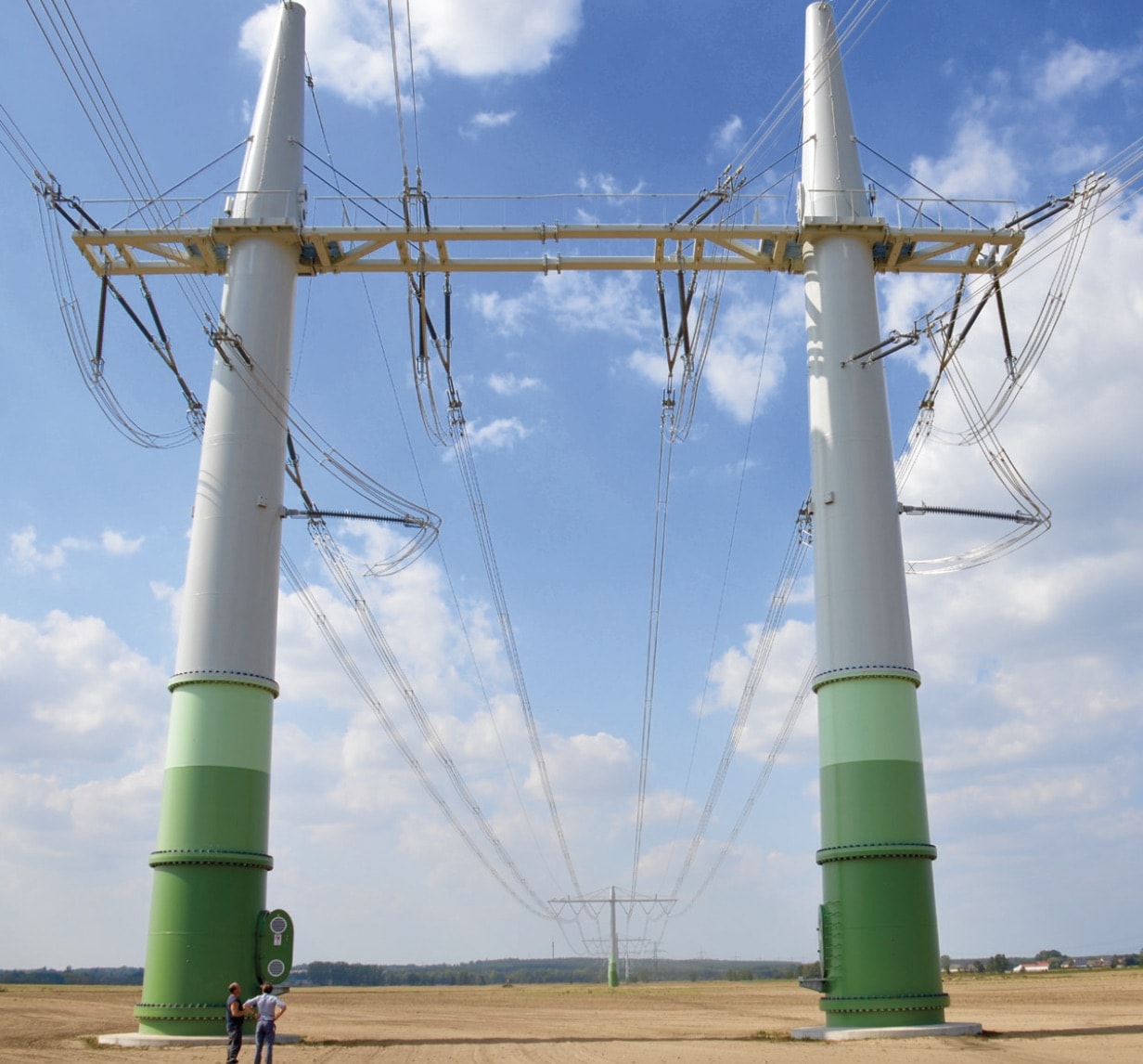
At the same time, another essential goal was reducing bottom dimensions of towers. In the end, the suspension tower was designed as a tubular, conical steel pole with ring flange connections while the dead-end tower was portal type consisting of two tubular conical steel poles supporting the cross-arm. Both designs are based on concepts proven from years of experience with wind turbine towers. Cross-arms consist of steel profiles connected to the tower top by steel tie rods. Manholes at tower bottoms and tops allow worker access to cross-arms without need for cranes or lifts – another basic pre-condition of the ideal compact design. The resulting standard suspension tower has an overall width of 38 m and height of 30 m. The standard tension tower has overall width of 36 m and height of 36 m.
CLICK TO ENLARGE
CLICK TO ENLARGE
CLICK TO ENLARGE
Technical Achievements of New Design
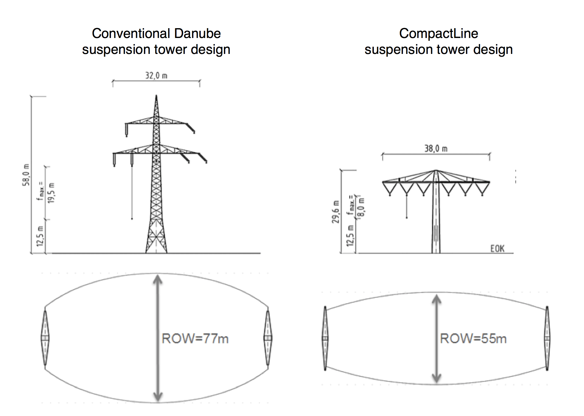
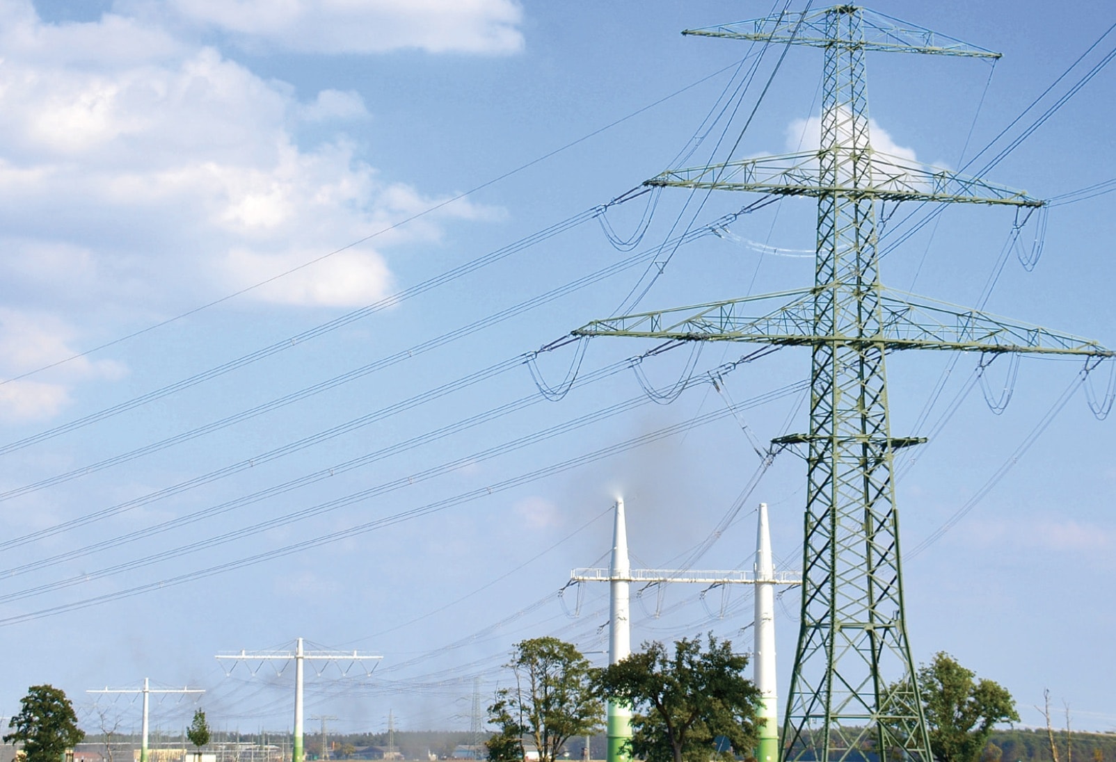
A great deal of engineering and testing was needed to fulfil all requirements of compaction while also ensuring that the components developed satisfied all applicable standards. Due to reduction in conductor sag combined with less lateral movement of the conductor bundle as well as the single level configuration of phases, tower dimensions have been significantly reduced and are much smaller in width and height compared to conventional 400 kV Danube towers. Required ROW has also been reduced.
CLICK TO ENLARGE
With reduction in suspension tower height, i.e. from 58 m to 30 m, and average ROW from 77 m to 55 m, key project objectives were achieved. With this innovative design concept, it has become possible to replace existing 220 kV double circuit overhead lines with a 400 kV double circuit line – without increasing ROW. Such a compact overhead line design has also reduced impact on the environment. Correspondingly, it is likely that the reduced overhead line geometry might also positively influence public acceptance.

Communication Concept & Acceptance Study
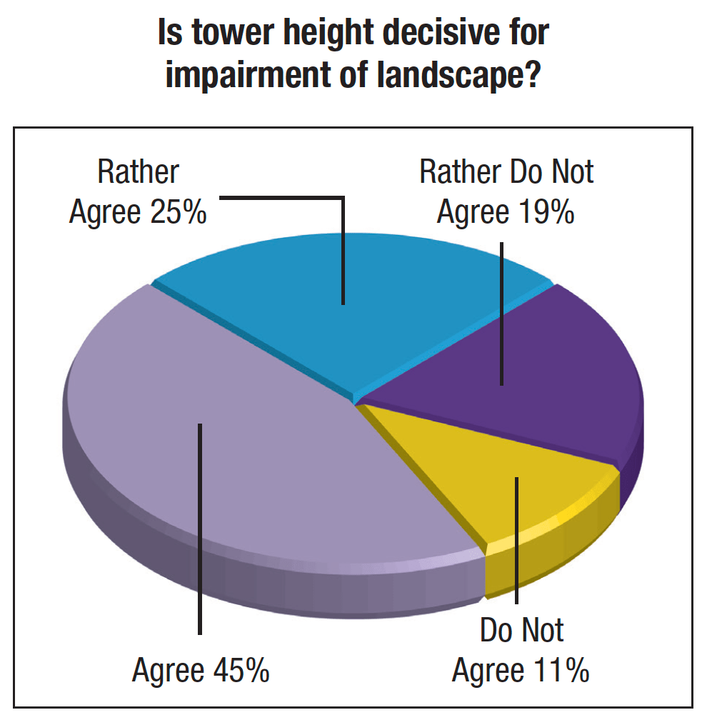
To understand which factors are most relevant for public acceptance of new overhead lines and whether compactLine could indeed be a positive contribution, an independent university-based institute conducted a one-year field study. This research examined acceptance of overhead lines in general and compared compactLine to conventional designs. Researchers began collecting background and data by interviewing stakeholders such as technicians, environmental experts and municipal administrative bodies. This generated a range of factors and parameters that influence acceptance of overhead lines. Based on these, workshops with politicians, media and other stakeholders were conducted to better elaborate these factors and develop a comprehensive questionnaire for use in a survey of nearly 1000 participants selected at random from different parts of Germany. One goal of the questionnaire was to identify those parameters with highest relevance for acceptance of overhead lines; another was to specifically compare the new compact line with a conventional Danube tower. Analysis of survey results revealed that, among the 47% of survey respondents who showed a preference for one type versus the other (53% were indifferent), 85% preferred compactLine. Another conclusion from the survey was that tower height (i.e. visibility of the overhead line) is decisive in terms of landscape impairment and therefore will greatly influence public acceptance or opposition to a new line.

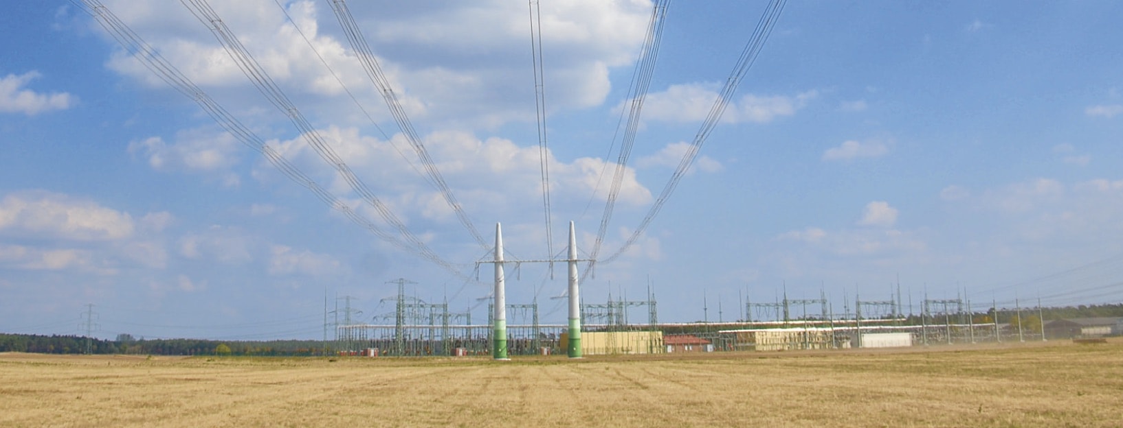
Pilot Installation
Upon finalization of technical development and the positive findings coming from the acceptance study, a decision was made to demonstrate the concept in practice by means of a pilot installation. Located in a mainly agricultural area south of Berlin, this installation is approximately 1.8 km long and consists of 5 towers, three suspension and two tension towers. It became fully operational in autumn 2018 and serves to connect an existing substation and a nearby conventional 400 kV overhead line. An extensive monitoring program has been set up to analyze operational behaviour and gain experience for future operation and maintenance. Operating parameters being continuously monitored by sensors include sag, corona, noise, insulator stress and tower bending. These measurements are being combined with visual inspections at two-month intervals.
CLICK TO ENLARGE
Analysis of Influence on Environment & Health
Along with on-going monitoring at the pilot installation, further study will be done by an independent consulting firm on influence of overhead lines on the environment. In this regard, the pilot installation will be compared to two existing conventional overhead line connections (400 kV and 220 kV) in terms of impact on local population and health as well as on biodiversity of local flora and fauna, etc. The goal is to gain more knowledge on possible interdependencies.
CLICK TO ENLARGE
CLICK TO ENLARGE
Conclusions
A new compact overhead line concept, called compact- Line, has been developed, simulated and extensively tested to satisfy operational requirements and assure continued high reliability. With this new design, it has become possible to condense a 400 kV overhead line into the dimensions normally occupied by a 220 kV overhead line and thereby reduce environmental as well as visual impact. An independent acceptance study subsequently confirmed the positive effect of this design on public acceptance of overhead lines. Due to these results, a pilot installation was constructed and commissioned in late 2018 to allow monitoring of all key operational parameters.
References
City Analytics: City Analytics (ed.) workshop presentation: “Innovative Freileitungen – Was die Menschen denken, Ergebnisse der Akzeptanzstudie“, Berlin 2016
Golletz, F. et al: CIGRÉ 2016, B2-307: “CompactLine – a new Overhead Transmission Line Concept”, Paris 2016
Kiewitt, W.: CIGRÉ WG B2.63 Meeting, May 2017 – “CompactLine – Development of a compact 400kV overhead line”, Dublin 2017