Over recent years, a number of factors have come to influence how new overhead lines are planned, designed and built. These factors include the growing need to integrate renewables into the grid, moving as much power as possible along existing corridors and keeping structures as compact as possible. Overlapping these requirements is heightened awareness of safety as well as ensuring that all line components and equipment operate reliably over their expected service lives.
A project in Belgium that INMR visited in late 2016 exemplified how the country’s transmission system operator succeeded in meeting these goals and challenges.
The new double circuit 380 kV line that transports power between the Stevin Substation in Zeebrugge and the Horta Substation near Zomergem is not the type of project that might normally attract much attention. Yet with only 100 towers and covering but 37 km of overhead line along with 10 km of underground cable, it soon became among the most watched T&D projects in Europe. What made the project so interesting is that it offered an excellent example of how a power utility can adapt to meet the challenges faced by most in the electricity supply industry – from helping respond to climate change to dealing with public opposition to new lines and structures. In this context, the processes and solutions used offer an opportunity to study how these types of challenges can be approached and overcome.
CLICK TO ENLARGE
CLICK TO ENLARGE
Among the main drivers behind the Stevin Project was connecting the Belgian power grid to about 800 MWA coming from existing offshore wind farms and photovoltaic facilities in the country’s north. Another was to link to 1200 MWA of additional power anticipated from new offshore wind generation expected to have come on stream by this year. Other considerations included connecting to the 1000 MW Nemo Link with the United Kingdom as well as meeting increased demand for power in the developing port city of Zeebrugge.
[inline_ad_1]
Against the backdrop of these requirements, Belgium’s TSO, Elia, had to obtain approval to build a new line in a small, densely populated country where, like elsewhere across Europe, there is strong public resistance to new overhead lines. In the end, the solution adopted involved re-using towers along a 16 km long existing corridor, laying 10 km of underground XLPE cable and building 21 km of new compact structures that employ pivoting and non-pivoting assemblies of composite insulators. As compensation for obtaining the necessary approvals, Elia dismantled 53 km of existing 150 kV line running through the same corridor and also placed 35 km of formerly 150 kV overhead line underground.
CLICK TO ENLARGE
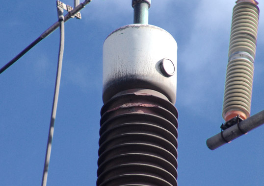
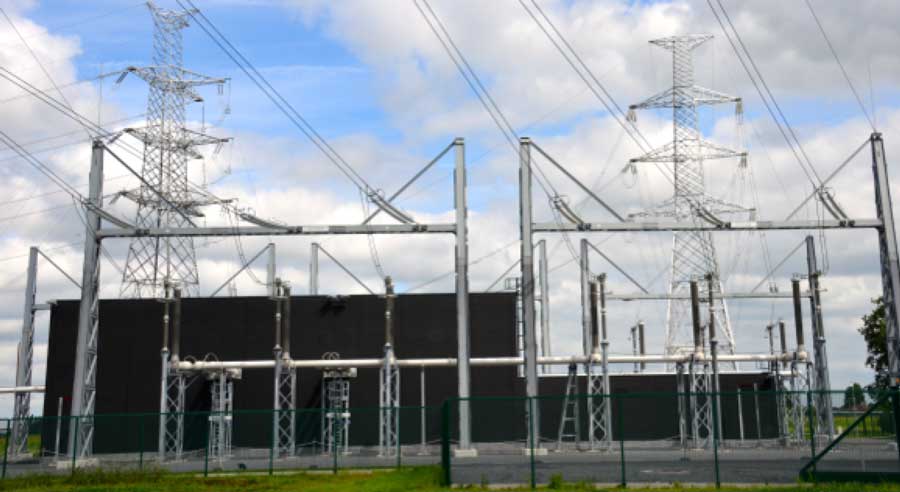
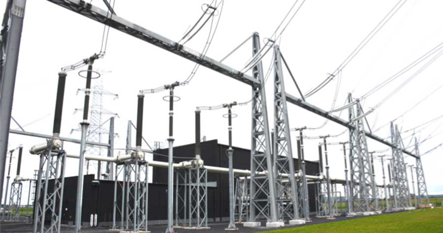
The Stevin Project also saw broad application of GIL and GIS technologies with the goal of reducing the footprint of new substations while also allowing them to better integrate into their surrounding landscapes. For example, the Horta Substation helps manage flux at this node in the network and marks one end of the new line. Like all new substations built these days in Belgium, it has been equipped almost entirely with composite insulators. The only application for porcelain is as station posts. The decision to require only composite housings for equipment was driven not by cost or pollution concerns but rather by safety considerations as well as reducing risk of collateral damage from explosive failures, such as occurred on current transformers in 2014 and again in 2016.
CLICK TO ENLARGE
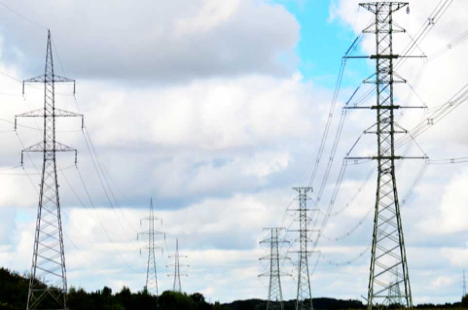
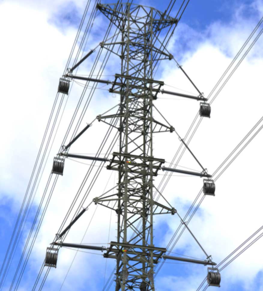
While the first section of the new line going to Eeklo Substation re-used existing structures that resemble those along an adjoining 380 kV interconnection with France (see Fig. 2), there are important differences. For example, it has been fully retrofitted with high temperature low sag (HTLS) conductor of 36.8 mm diameter compared to the previous 32.4 mm standard conductor. This changeover allows the line to operate at up to 150°C – double the normal maximum in Belgium. But it also created increased mechanical loads that required reinforcing cross-arms and structural members on 21 tangent towers and also replacing 8 of the previous angle towers. Elia engineers reported that they want to build up experience with these conductors with the goal of eventually applying them elsewhere on their network. However, to mitigate risk they chose to work with two different suppliers to allow relative performance to be compared. Elia is now among the world’s main users of HTLS conductor.
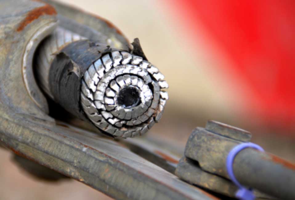
CLICK TO ENLARGE
Elia utilizes both aluminum conductor composite core (ACCC) and aluminum conductor polymer reinforced (ACPR) types, which carry similar price. For example, ACCC was installed two years ago on a 400 kV interconnection with the Netherlands and was also used on a new 12 km line to Germany. The technical characteristics of these conductors are a bit different and feedback will therefore be solicited from contractors in regard to comparative installation times as well as any difficulties encountered. This will help Elia determine all cost elements for each type, apart from only acquisition cost. Evolution of sag on certain spans will also be measured to see how each conductor type behaves in service.
[inline_ad_2]
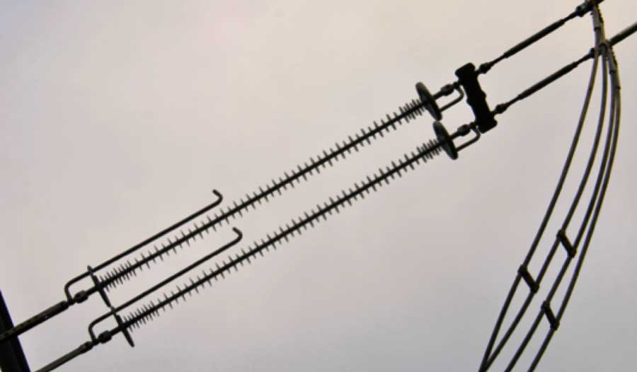
Another important change on the section of line between Horta and Eeklo Substations is in the insulation. While Belgium has traditionally been a user of glass strings, all insulators here are silicone composite type. One of the main drivers in this case was acquisition cost and indeed the new tension and suspension strings proved to be about half the price of glass alternatives. In spite of such savings when changing over to composite strings, engineers note that they will have to monitor whether or not their life cycle costs prove to be advantageous as well.
CLICK TO ENLARGE
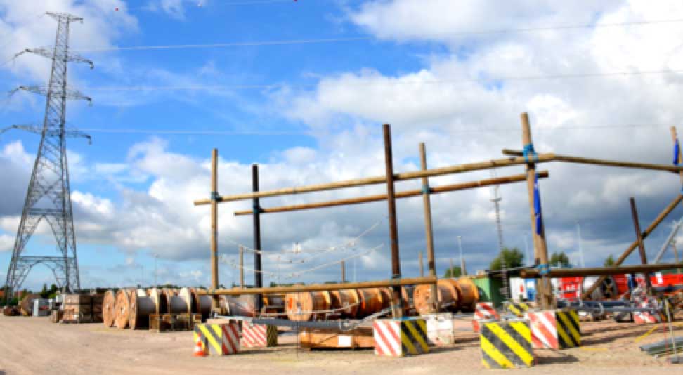
The nearby Eeklo Substation is connected to Horta by one 380 kV circuit that was energized in May 2016. The second circuit from Horta bypasses Eeklo and connects to the van Maerlant Substation that marks the start of a 10 km section of underground cable. Eeklo served as the principal construction hub for the overhead line segment of the project. Equally important, it was a center to ensure that all construction personnel were made familiar with the new components and followed the same procedures when handling and installing them.
CLICK TO ENLARGE
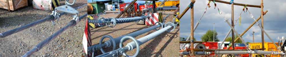
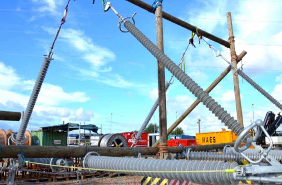
Built years ago as a conventional air-insulated substation, examples of each different conductor and insulator configuration used on the Stevin Project were set-up on wooden structures. This allowed crews to see the correct configuration for each type of installation and how it should be mounted, something that was later verified on-site by line inspectors. Apart from proving highly effective in this respect, another benefit was that it allowed Elia staff to check that all incoming shipments were delivered complete, with no items missing or incorrect.
CLICK TO ENLARGE
[inline_ad_3]
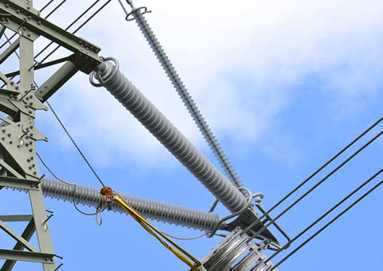
When it came to the insulator assemblies used on the Stevin Project, Elia chose a policy of purchasing the complete system from designated suppliers, including not only the insulators but also corona rings and other fittings. A similar philosophy was applied for the HTLS conductors that were delivered along with armor rods, suspension and tension clamps and bolts. Insulators, particularly the pivoting and non-pivoting insulated cross-arms that formed the basis of the compact segment of the new 380 kV line, were regarded as critical assets. Therefore, as in the case of the HTLS conductors, it was decided to mitigate risk by purchasing these from two different sources and equipping each circuit only with insulators coming from the same manufacturer. That way, if some unforeseen problem was discovered with the insulators provided by one of the suppliers, it would not affect both circuits and these would not be lost at the same time. In fact, all decisions made about line insulation received special attention in view of some industry reports of reliability problems experienced with composite insulators. To overcome such risk, there was a great deal of checking into all potential suppliers followed by full-scale testing in cooperation with experts.
CLICK TO ENLARGE
CLICK TO ENLARGE
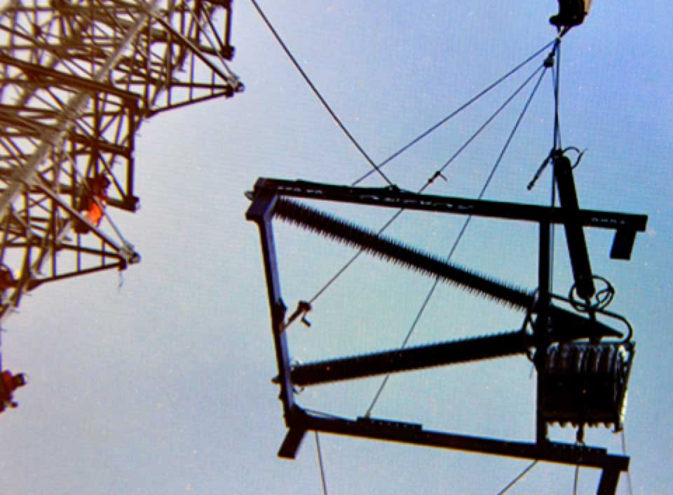
CLICK TO ENLARGE
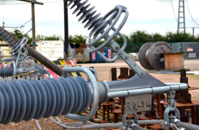
One of the experts consulted was Dr. Igor Gutman who was closely involved in helping arrive at the final specifications for insulators and also in checking the test reports submitted by suppliers. Gutman explained that while the classical niche for composite insulator technology has been for polluted service environments, this has begun to change to also include insulation coordination. “Cross-arms, arrays and even entire structures are now a new area of application for composite insulation technology,” he noted. “In this case, we were looking at lines in clean service areas and where the main concern was water drop corona as well as related tracking and erosion. But during the time frame of this project there was still lack of standardized criteria for maximum permissible electric field to prevent corona from metal fittings on the composite housing.”
CLICK TO ENLARGE
CLICK TO ENLARGE
Gutman explained that research conducted at STRI in Sweden, in parallel to similar work by EPRI in the U.S., arrived at basically the same criteria – namely 1.8 kV/mm maximum permissible E-field from metal and 0.4 kV/mm from the housing. Otherwise, there is risk of permanent corona from water drops in clean areas. The result will be loss of hydrophobicity in about 5 years and risk of erosion in critical areas in about 10 years. These predictions of ageing are only accelerated under contaminated conditions.
[inline_ad_4]
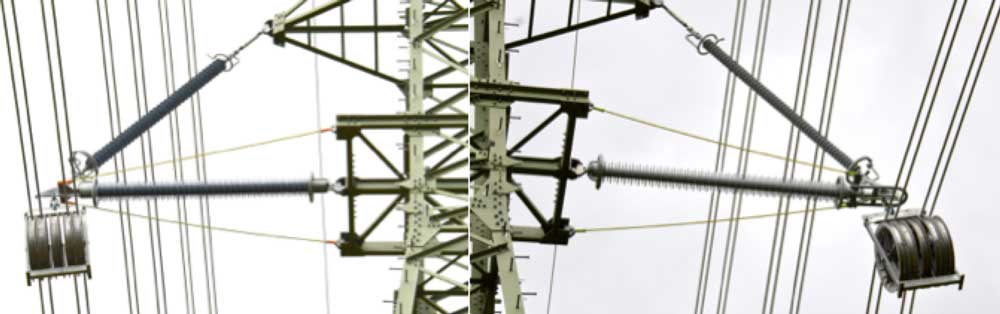
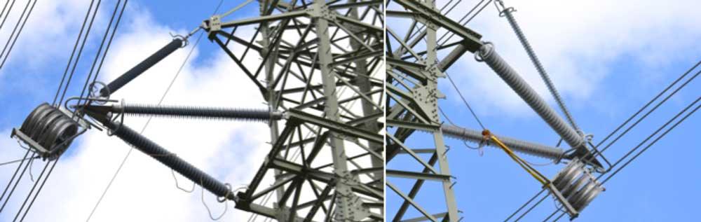
Different insulator designs were used on each circuit of the Stevin Project. For example, one saw the insulators manufactured by slipping sheds over a silicone-extruded FRP rod while the other has the entire housing molded directly onto the rod itself. Also, one uses an HTV silicone housing while the other is made from liquid silicone rubber (LSR). Finally, rod sizes are also different, with those used for the HTV units having a diameter of 130 mm while 110 mm diameter rods were used on the LSR insulators. Elia engineers reported that one of the early findings was that the HTV material is a bit more resistant to shocks and handling while LSR is somewhat more sensitive to minor damage. The two also have different weights, with the HTV silicone assembly weighing up to 25% more. The lighter unit is more advantageous from the viewpoint of the contractor but, apart from that, the two assemblies have been found comparable in terms of ease of installation.
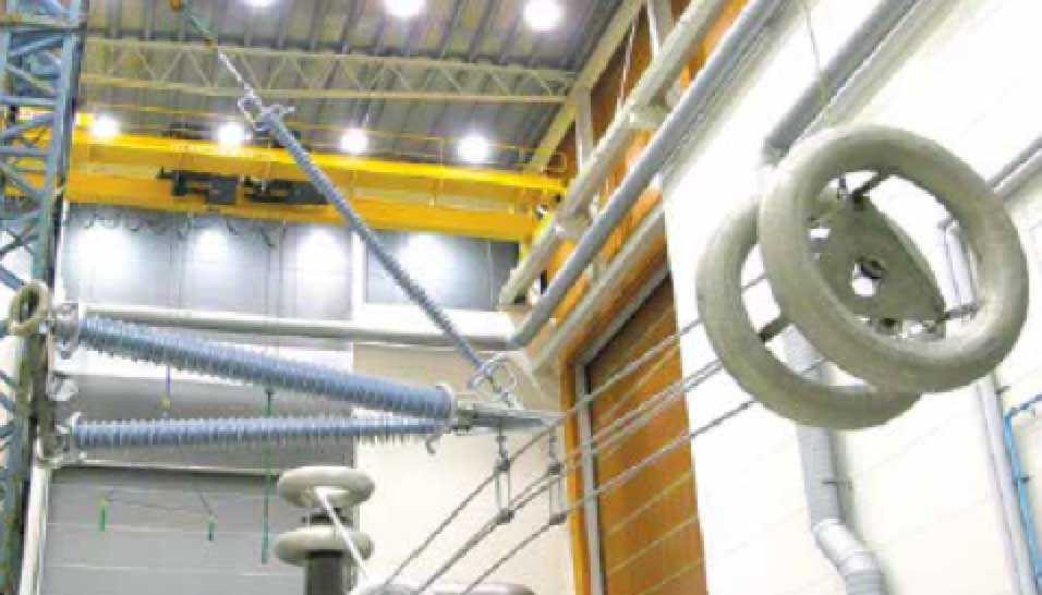
According to Gutman, the insulated cross-arms were dimensioned specifically not to experience corona and this involved a great deal of electric field calculation. In addition, a special test was developed to verify the results of these calculations using full-scale models equipped with corona rings. It is very important for complex structures such as these to verify design using 3-D field calculations and, in fact some designs had to be re-done based on what was found. Basically, limits were specified for different points along the insulators to make sure these limits were always maintained. This not only prevented excessive noise but also any corona activity that might affect long-term insulator performance.
CLICK TO ENLARGE
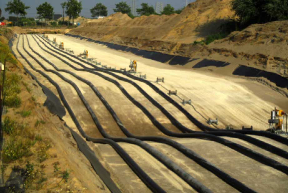
Another key element of the Stevin Project was the 10 km section of 4 circuits of XLPE cable that allow the line to bypass the historic city of Bruges. As with conductors and insulators, the same risk mitigation philosophy was applied by choosing two different suppliers who were each awarded two circuits. Moreover, a real-time monitoring system was required by the government for this first-ever installation of 400 kV cable in Belgium.
CLICK TO ENLARGE
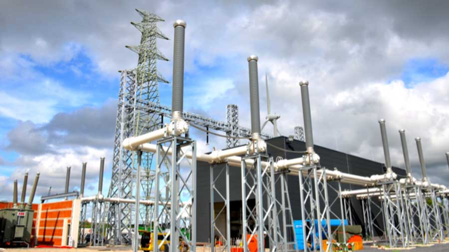
The Project terminates at the Stevin Substation in the coastal city of Zeebrugge. Named after 16th century Flemish mathematician and physicist, Simon Stevin, the GIS substation was sited at a low point near a highway overpass to reduce visual impact. Notwithstanding, it offers an elegant sweeping design that resembles a ship. As at other substations on this project, it utilizes GIL to reduce distances between incoming phases and allow for smaller overall footprint.
CLICK TO ENLARGE
CLICK TO ENLARGE
In regard to plans for inspecting the new line, initial guidelines involved a combination of visual inspection and hydrophobicity measurement whenever a circuit is taken out of service. This was not the first time Elia has used composite insulators since these were first specified on projects starting about 8 years ago. The major trigger for going with these insulators in the case of this particular project was the insulated cross-arms. But because of lower acquisition costs, it has now become policy at Elia to also use them for all new lines of 150 kV and higher as well as on refurbishment projects such as when re-conductoring lines. Feedback from construction contractors has been positive and, although insulator acquisition cost has been lower, inspection and maintenance costs are expected to be higher given that this is still a relatively new technology. Elia engineers expect a minimum 50-year life for the Stevin Project.