Cable accessories perform the key function of ensuring required insulation either at the connection points of cables (straight joints) or at their ends (terminations). These accessories have to be easy and safe to install over a broad range of different cable cross-sections and ideally should consist of as few components as possible. Since the start of the shift away from medium voltage (MV) paper-insulated cables and toward polymeric cables more than 45 years ago, there have been a steadily increasing number of different types in use throughout the world. For all these different cables, successive generations of accessories have been introduced. Heat shrink technology, with polyolefin material used for terminations as well as joints, was gradually replaced by slip-on and cold shrink technology, using either silicone or EPDM. For example, the substitution of air-insulated switchgear by gas-insulated switchgear (GIS) led to the replacement of terminations by separable connectors made from these polymers. Due to the increasingly large variety of different types of cable accessories, questions naturally arose as to which offered the best material, the best installation technology and the optimal design for each application. Since the answer in each case depends on application requirements and service conditions, this has naturally been a topic of debate within the industry. This past INMR article outlined the advantages and disadvantages of different material combinations and design features as they apply to MV polymeric cables, with focus on outdoor terminations and straight joints.


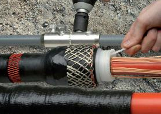
To better appreciate the diversity of MV cables available these days, it is useful to examine their different components. As evident in Fig. 1, which shows but a small sample of the many different cables now available, the conductor can be copper or aluminium, with a solid or a stranded conductor and with rounded or sector shape. Standard cross-sections vary from 10 mm² up to as much as 800 or 1000 mm², although the large majority of MV cables in use today fall between 95 and 300 mm².
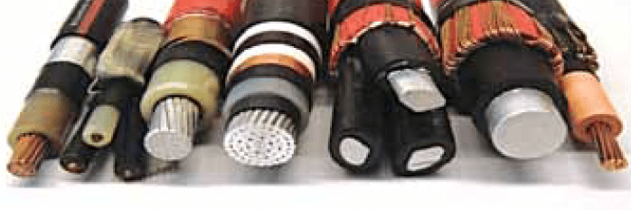
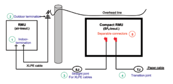
The insulation material and inner and outer semi-conductive layers of cables are generally made of cross-linked polyethylene (XLPE) or ethylene propylene rubber (EPR). The outer semi-conductive layer can be fully bonded with the insulation (removable only with a special tool) or strippable by means of knife, which is the case for most sector shaped and EPR cables. Typically, the screen for single and three core cables consists of copper wire, but it can also be made of copper tape, aluminium tape, aluminium wire, copper or steel mesh or even a lead sheath. Some three-core cables have armouring using steel wire or tape while single core cables usually have armouring made of a non-magnetic material such as aluminium wire. The outer sheath material can be PE or PVC, available in different colours. Accessories for MV cables should ideally be applicable over this wide range of different cable types and constructions. Fig. 2 outlines some of the most important applications, including:
1. Indoor termination, i.e. connecting a cable with air-insulated switchgear
2. Outdoor termination, i.e. connecting a cable with an overhead line
3. Straight joint connecting two cables
4. Transition joint, i.e. connecting polymeric with paper-insulated cable
5. Separable connector, i.e. connecting a cable with a gas insulated switchgear
In certain cases, the number of accessory variants can effectively be reduced by using only one type for different voltage classes, different cross-sections and even different applications (e.g. outdoor termination for 24 kV or alternatively indoor termination for 36 kV). While paper-insulated cables are still in use in some parts of the globe, even for new applications, their importance is declining rapidly. As such, the following review does not cover accessories for this technology.

Stress Control
With increasing voltage beyond 10 kV, the problem of electrical field control (or stress control) has become more and more important and a major requirement in the design of cable accessories. Fig. 3 shows the main components of a MV cable.
Because of components 2, 3 and 4 in a MV cable, the internal field is slightly non-homogeneous (see sectional drawing at right of Fig. 3).
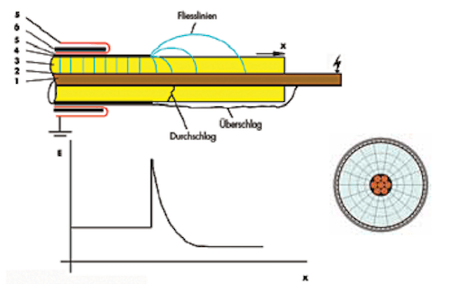
In order to install a joint or termination, it is necessary to remove the outer semi-conductive layer along a certain length. At this end of the outer semi-conductive layer (i.e. the cut edge), electric field intensity increases considerably (see function E along the cable insulation surface). To reduce this field intensity, two different solutions are considered suitable. One sees geometric field control (Fig. 4a), using a stress cone made of semi-conductive material. The other involves refractive field control (Fig. 4b) using a tube of an insulating material with a dielectric constant between 10 and 20. The advantage of the former is that it represents a loss-free solution that is also suitable for high and extra high voltage. On the other hand, it requires more material consumption and is not that good a solution for multi range type accessories. Refractive field control (b), by contrast, is a good solution for a wide range of different MV cable diameters because of its slim tube construction. This type of field control can compensate for any mistakes made during cable preparation (such as shown in Fig. 5) but will also result in low thermal losses at this critical point in the termination.
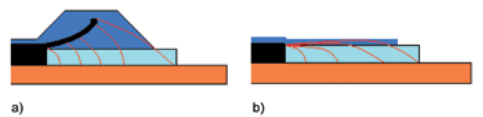
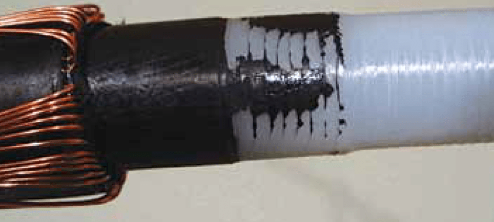
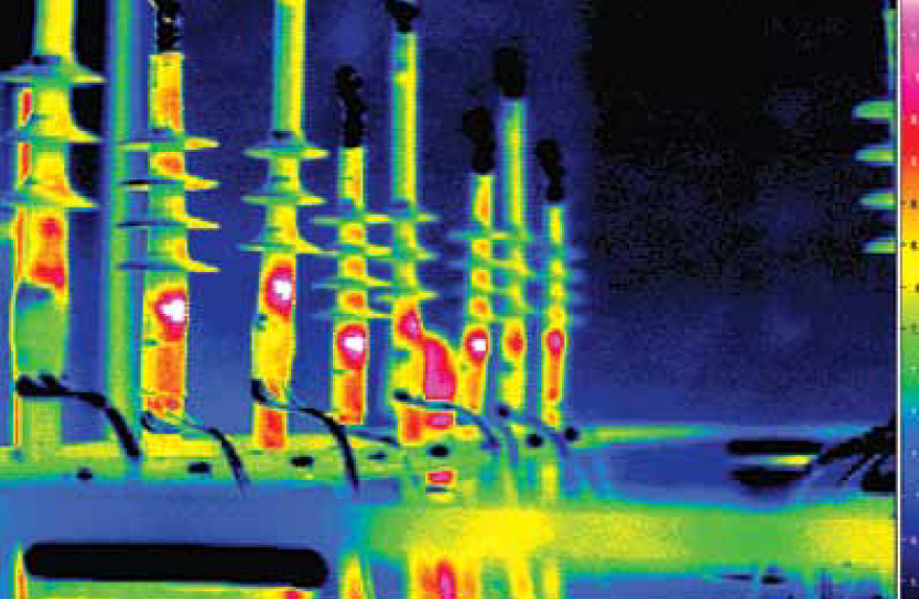
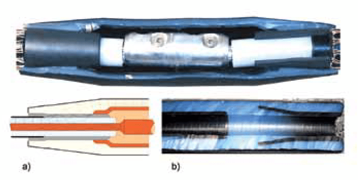
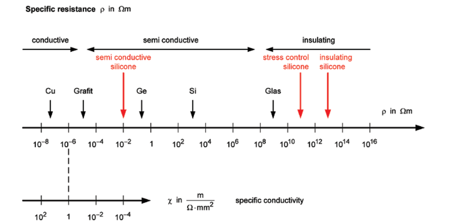
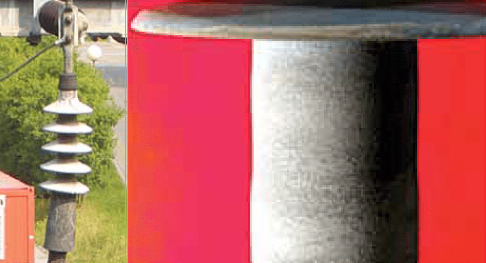
Fig. 6 shows such thermal losses on a photo taken by an IR camera (see the white temperature indication in the stress control area of different terminations). Temperatures increase in this area by more than 1°K but less than 2°K (in the case of a test voltage of 1.5 U0). While such a rise is considered moderate and not critical for most MV applications, it becomes more problematic as voltage levels increase. That is why this type of stress control is not currently considered suitable for high and extra high voltage accessories. Fig. 7 illustrates two practical joint solutions – the first relying on a refractive stress control tube, which connects the outer semi-conductive layer of the cable with the inner semi conductive layer of the joint using an insulating material. The second uses a geometrical stress cone made of semi-conductive material, as in the inner semi-conductive layer of both joints. Fig. 8 depicts a specific resistance scale for different materials with the resulting indication for an insulating silicone, a stress control (refractive) type silicone or a semi-conductive silicone.
In the final analysis, there are two different solutions for electric field control suitable for MV cable accessories, each with advantages and disadvantages. Their feasibility and reliability in each case is determined by proper design and correct material configuration. Indeed, only the right combination of design and material will assure the required performance when it comes to electric stress control.

Terminations
Terminations are a second important category of cable accessory and, in the case of outdoor applications, they have to fulfil several user requirements at each voltage level:
• availability in only one size, even across a range of cable cross-sections;
• high flashover voltage;
• long creepage distance;
• resistance to tracking and UV radiation;
• excellent behaviour under pollution, rain and fog;
• easy installation.
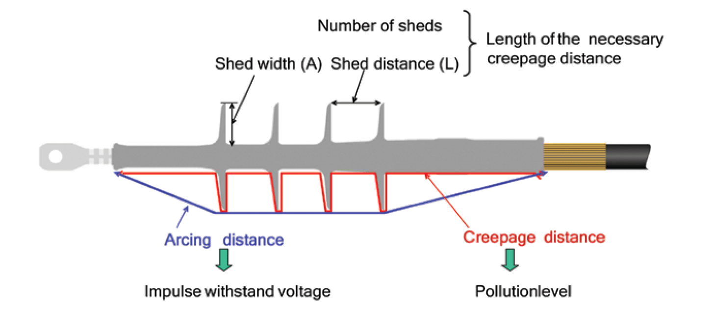
Fortunately, all these requirements can generally be met by either single piece or modular-type terminations. From the manufacturing point of view, these can be offered in a choice of insulating material, whether EPDM or silicone, although optimal production conditions are critical for both these materials. The essential design parameters of an outdoor termination are shown in Fig. 9 and include:
• core dimensions;
• number & geometry of sheds;
• distance between sheds.
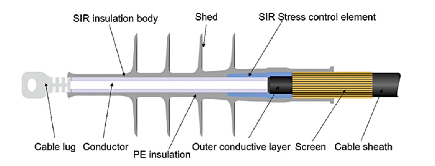
A sectional view of a termination with refractive stress control is shown in Fig. 10. Terminations with geometric stress control and similar design are also available for these voltages. Due to the impact of environmental factors such as pollution or prolonged sunlight, outdoor terminations must be specially designed to withstand surface stress caused by tracking or radiation. Formation of conductive carbon paths is due mainly to partial discharges. In the case of silicone rubber, no free carbon is formed upon degradation since it is removed as gaseous by-products. That is why eroded paths can form with no resulting conductive carbon (see Fig. 11 b). Use of EPDM for a cable termination can, however, lead to such conductive carbon paths (as in Fig. 11a) and therefore a much longer creepage distance is required.
The extent of surface damage on an outdoor termination depends on leakage current and here is where the well-known property of hydrophobicity becomes very important. Its impact can be seen in a comparison of salt fog test data for two different 24 kV outdoor terminations (see Fig. 12).
In general there are a number of different standardized tests for MV outdoor terminations. A recommended one, for example, is the salt fog test according to the CENELEC standard, with the following parameters:
4 samples arranged in a fog-chamber with a bushing
test-voltage: 1.25 U0
fog conductivity: 16 mS /cm (10g NaCl /l)
spreading rate: 0.4 l/m³ h
test duration: 1000 h
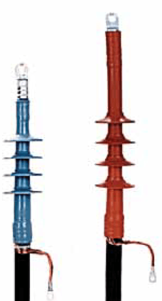
This particular test was carried out for the two different terminations shown in Fig. 12. The one on the left is a single piece silicone termination for 24 kV, the other a hybrid-type consisting of a heat shrinkable tube combined with silicone sheds. Leakage current was recorded in order to evaluate the onset and development of any damage. As is evident, after a certain period of time leakage current increased rapidly as the surface became progressively less hydrophobic and a film of water began to form. This same behavior was recorded for both terminations tested. This suggests that leakage current level during the salt fog test is independent of material and rather only a function of test conditions as well as insulation dimensions (i.e. diameter and length).
To confirm this, immediately following the 1000h test flashover voltage was determined for both types of terminations under wet conditions. The specific flashover voltage was found to be somewhat higher than 0.6 kV/cm for both terminations with different shapes and different insulating materials (see Fig. 13). But, after a recovery time of about 70 hours without wetting to give the low molecular weight components in the silicone time to migrate to the surface, the single piece type showed complete recovery of hydrophobicity. The insulation was humidified again and this time flashover voltage increased to 0.93 kV/cm. For the hybrid type, by contrast, only the sheds became hydrophobic again and that is why the increase in flashover voltage was lower (0.77 kV/cm) even if the impact of hydrophobic sheds was itself quite significant.
![Figure 13: Specific flashover voltage [kVpeak/cm] of terminations under wet conditions at end of salt fog test and after ‘recovery’ period.](https://www.inmr.com/wp-content/uploads/2016/07/Screen-Shot-2016-07-06-at-14.30.24.png)
Given the above, the following advantageous properties of silicone should always be taken into account in the application of outdoor terminations:
• resistance to ultraviolet radiation;
• resistance to tracking;
• hydrophobicity of the surface;
• recovery of hydrophobicity, even after years;
• transfer of hydrophobicity into any contamination layer.

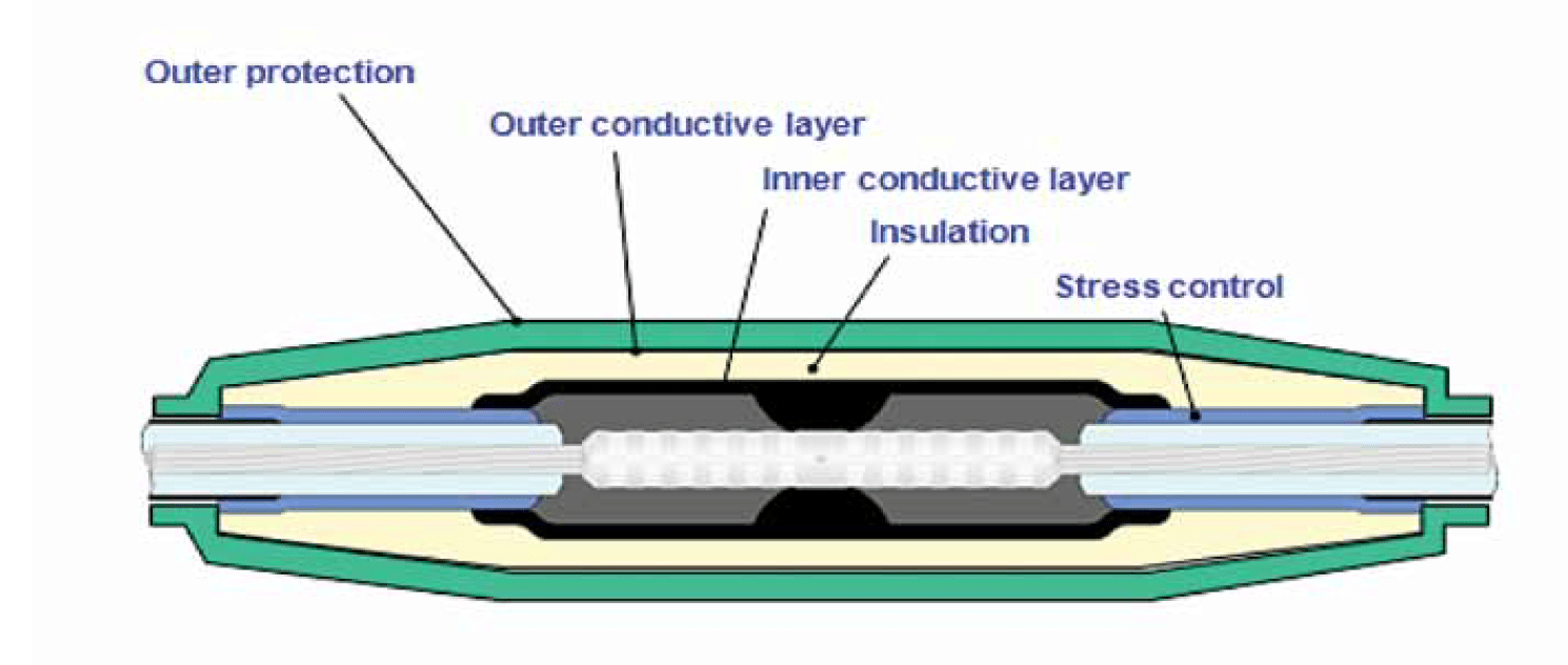
Straight Joints
In the case of cable joints, other material properties become important (see Fig. 14 which shows the main components). The stress control element can be refractive or geometric (as per Fig. 7b) and either silicone or EPDM can be used for the inner semi-conductive layer, the insulation and the outer semi-conductive layer.
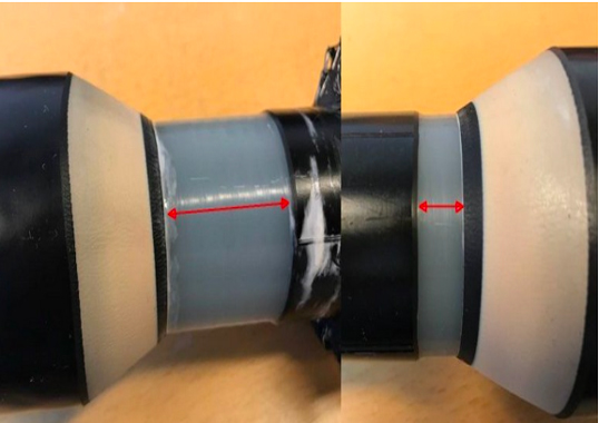
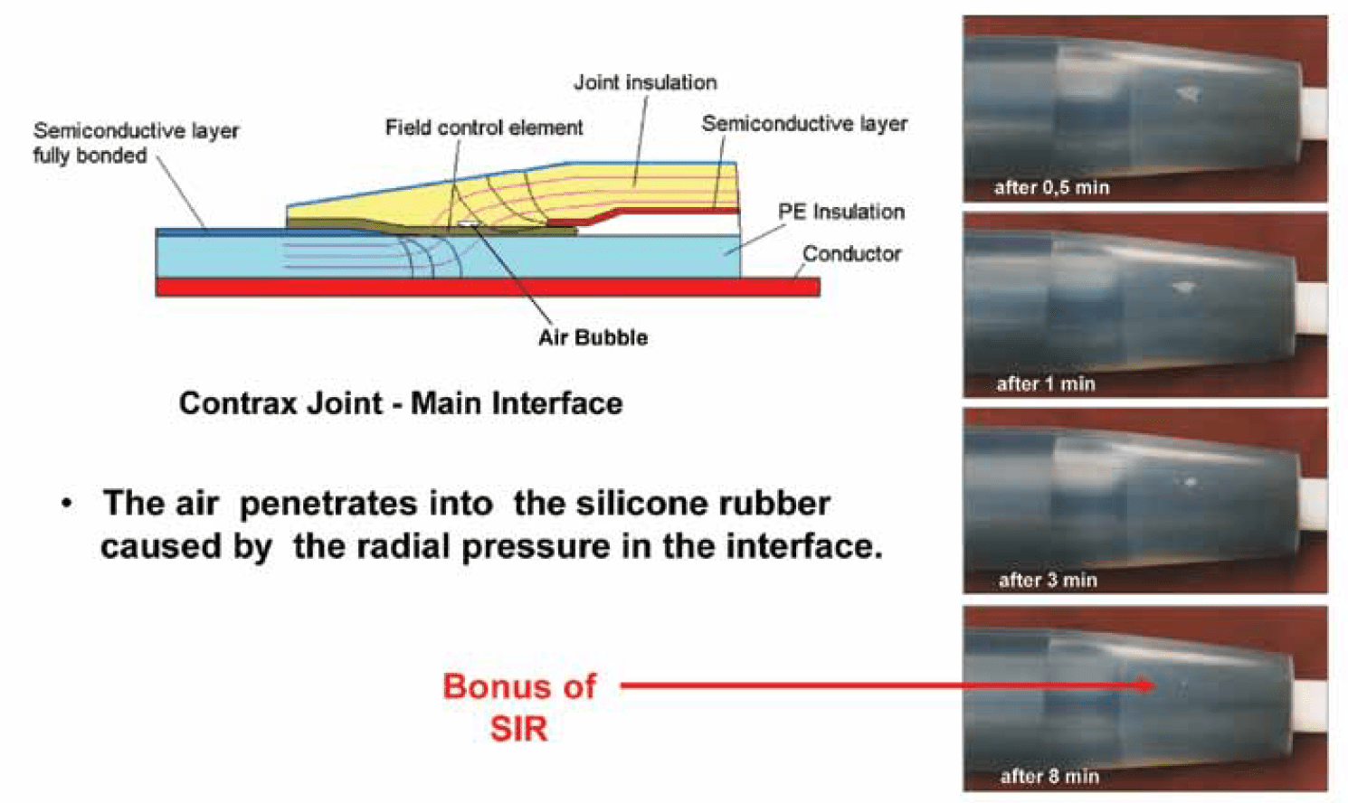
One important advantage of silicone for this application, however, is its superior rate of gas penetration. This means that any gas bubbles trapped in different joint interfaces will quickly disappear due to the radial pressure of the silicone components. Fig. 15, for example, shows an air bubble at a critical joint interface. Using a transparent joint body, it becomes evident that the bubble disappears in less than 10 minutes. This ensures that the interface is free of any air enclosures soon after assembly – yielding a high value of partial discharge inception voltage as well as a high functional reliability. For the outer protective tube of the joint, however, silicone is not appropriate since the same gas penetration rate, which is an advantage for the insulation body interfaces, becomes a disadvantage in terms of outer protection. The permeability of silicone to water vapour in particular makes it unsuitable for this application and EPDM is preferable.
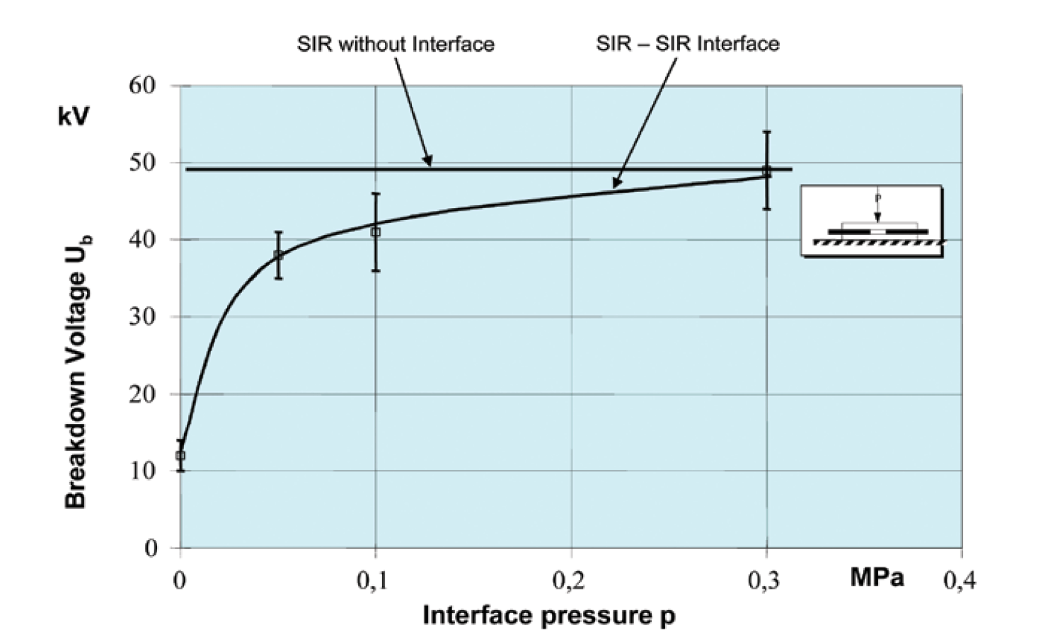
Another design problem to resolve when it comes to joints is breakdown voltage in different interfaces and this leads to a choice between a single piece versus a modular solution. Fig. 16 demonstrates that a silicone-silicone interface under a certain pressure has the same breakdown voltage as a single piece solution without interface. Therefore, a modular joint should have the same reliability as a single piece joint in the case of silicone. If the preferred joint material is EPDM, however, a single piece solution is recommended.
In order to benchmark different solutions and materials, an approved test procedure is typically used. Lifetime curves for a silicone-to-silicone interface and a silicone-to-stress control compound interface were measured by stepwise increasing voltage with different step durations. The test showed that both types of insulation system have basically the same lifetime and very good long-term behaviour. Indeed, the excellent resistance of silicone to electrical ageing was first published in a paper in 1996 and has since been confirmed by subsequent additional research using different arrangements, compounds and stress conditions.
In general, the following advantageous properties of silicone should be taken into account in the design and manufacture of cable joints:
• high degree of gas permeability ensuring no trapped gas bubbles in interfaces;
• high electric breakdown strength, even at the interfaces;
• very low decrease rate of service life even under fairly high electric stress;
• transparency which allows visual checks for any impurities;
• permanent elasticity resulting in constant interface pressure.
Summary
Modern MV cable accessories are made of elastic insulating materials that enable manufacturers to deliver pre-fabricated and tested products. This ensures high reliability with no maintenance as well as safety and long service life. During recent years, two different materials – silicone and EPDM – have become the dominant choice for MV cable accessory manufacturers and customers alike. In the end, both are suitable technically, depending on ambient conditions, although achieving the optimal mix of quality, reliability and low cost depends on finding the correct combination of design and material.
In the case of terminations, especially for outdoor application in slip-on or cold shrink technology, silicone dominates the world market due to its unique properties. In the case of MV joints, the use of silicone and EPDM materials is about the same for both slip-on and cold shrink technologies. The differences in material characteristics are not that critical here and price therefore becomes a factor. If one considers HV and EHV joints, however, the situation is different and the superior interface behaviour of silicone makes it the clearly preferred choice.
If one looks at separable connectors, not specifically discussed in this article, the picture is quite different. For the outer cone system, there are some silicone products on the market, especially in Europe and mostly in combination with a metallic enclosure. But worldwide, EPDM dominates the outer cone types of separable connectors. The reason for this is that material price is only one consideration and there are additional requirements: i.e. the separable connector must be fully screened and touchable to provide complete safety for personnel. This can best be achieved by an outer semi-conductive layer made of EPDM making it easier, more reliable and more cost-effective compared to silicone.