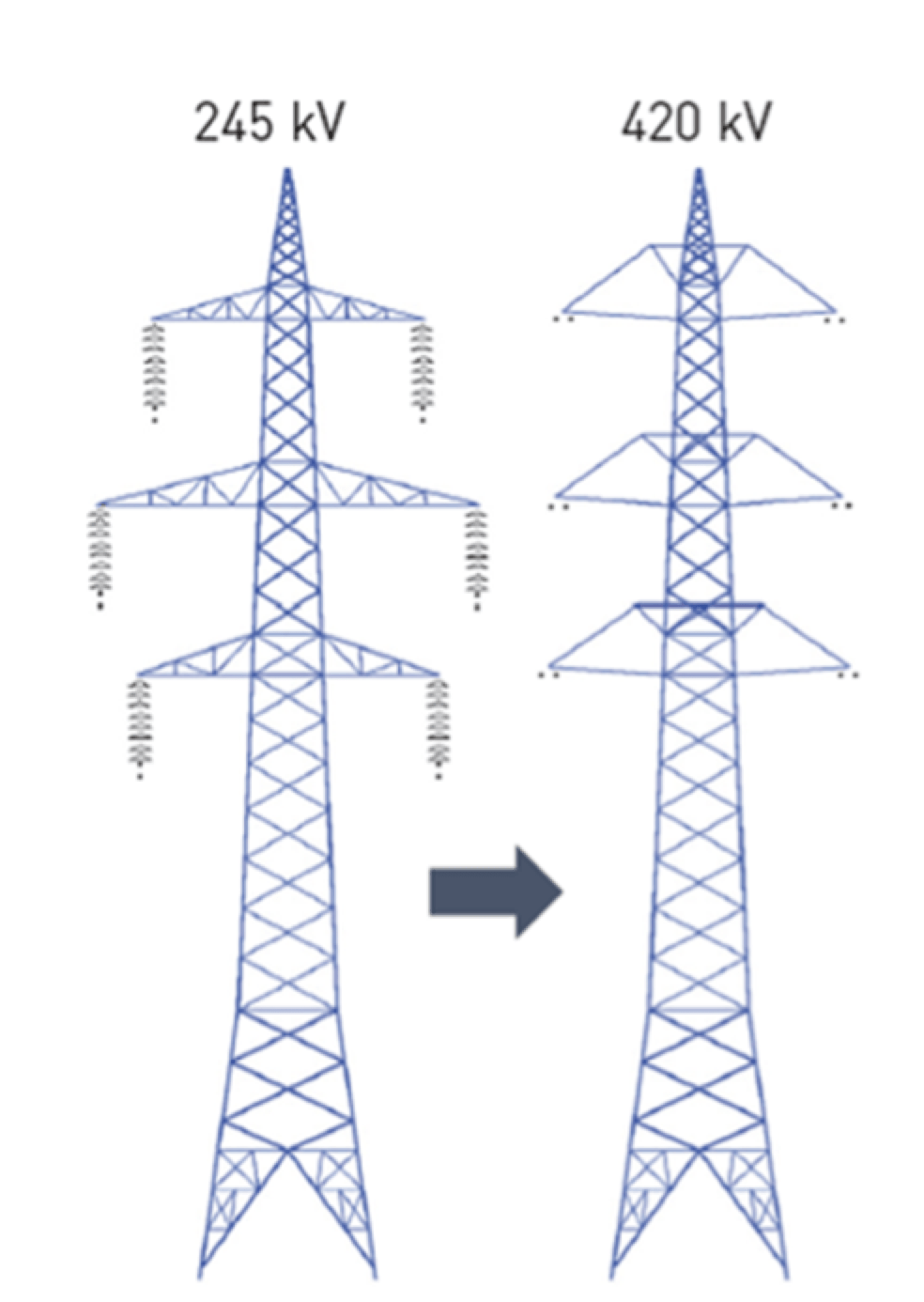
Because of increasing difficulties in securing approvals for new transmission corridors, various new technologies for line uprating have been developed and are now being implemented. The basic idea is to use existing line corridors to transfer more power. One possible option is to use high temperature low sag (HTLS) conductors to increase current and/or modify tower top geometry to increase voltage. In the case of the latter, composite insulators have offered new options. These enable design of HV insulated cross-arms that replace existing steel lattice cross-arms and also provide the additional ground clearance needed when line voltage is being increased.
CLICK TO ENLARGE
[inline_ad_1]
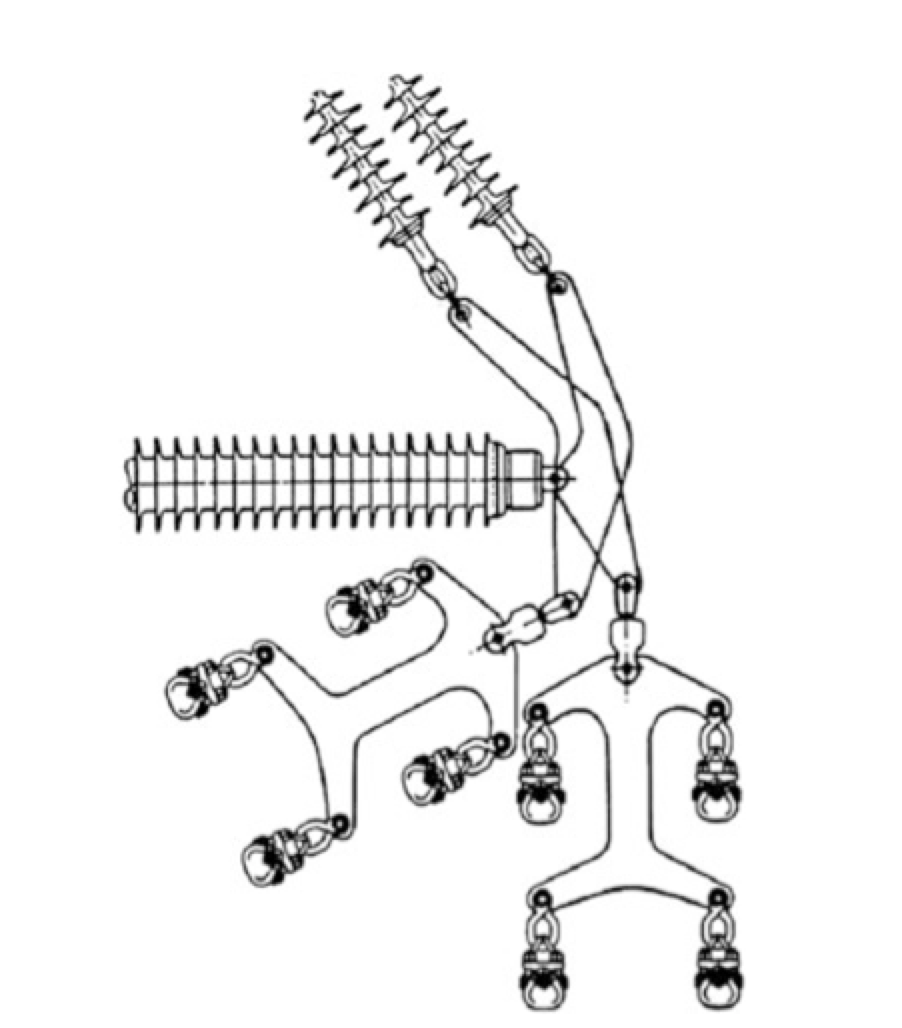
The advantage of composite insulators in insulated cross-arms versus insulators made from porcelain or glass comes from the fact that in such a cross-arm the post is loaded in compression. This can be sustained, in particular for high voltages (i.e. longer insulator lengths), only by using a composite insulator of suitable cross-section. In addition, composite insulators offer high bending strength, an elastic limit in the region of their ultimate strength and non-brittle behavior. All become important when an insulator is loaded in compression. But there are still issues to be resolved, such as stability of a line section with insulated cross-arms under strong crosswinds and unequal conductor tensions on adjacent spans. The proper solution in each case requires in-depth understanding of the problem and adequate software tools. Another issue requiring special attention is the eccentric application of the compression load to the post. This will cause it to bend excessively and, at the same time, reduce its load carrying capacity. A good engineering solution is to design the conductor attachment in such a way that the load will always be in the axis of the post.
CLICK TO ENLARGE
In practice, friction at the many joints of the cross-arm also has to be taken into account since it could have considerable effect on mechanical behavior of the cross-arm. This can only be reproduced sensibly by numerical simulation using the finite element method (FEM). On the other hand and due to the above mentioned uncertainties, it is recommended that insulated cross-arms be subjected to full-scale mechanical testing in addition to the type tests of their constituent insulators (post and brace), as stipulated in the various IEC Standards.
[inline_ad_2]
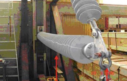
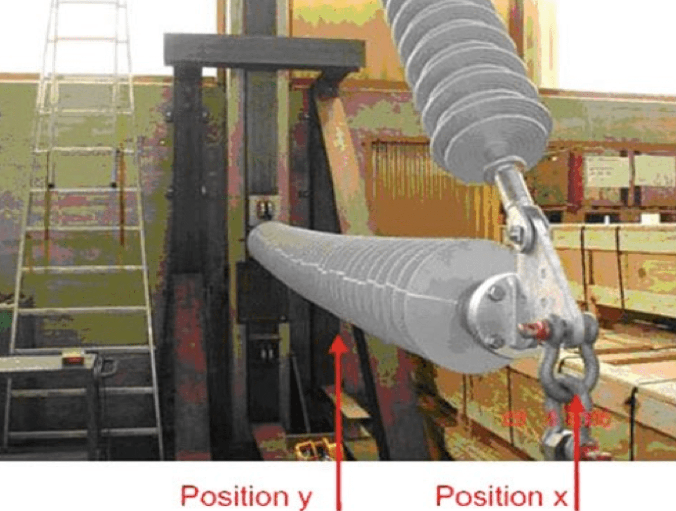
Specifically, the insulated cross-arm should be able to withstand the maximum allowable loads without permanent deformation or other damage. This should be verified by a procedure described in Section 6.3.1 of IEC Standard 61952, that is to say by applying for 96h the maximum allowable load of the structure increased by a safety margin of 10%. Once the test has been completed, the composite post insulator should be cut and examined in accordance with the method described in IEC 61952. The goal is to check for any internal damage, both in the vicinity of the two fittings and in the center of the rod, more specifically at the point at which maximum deflection was observed during the test.
CLICK TO ENLARGE
[inline_ad_3]
Insulating cross-arms with composite insulators are the only practical solution for uprating existing high voltage lines without need for extensive modification to support structures. Still, this application requires sophisticated design skills, manufacturing experience and also full-scale tests in order to verify the long-term reliability of the concept.
Contributed to INMR by Dr. Konstantin O. Papailiou
[inline_ad_4]