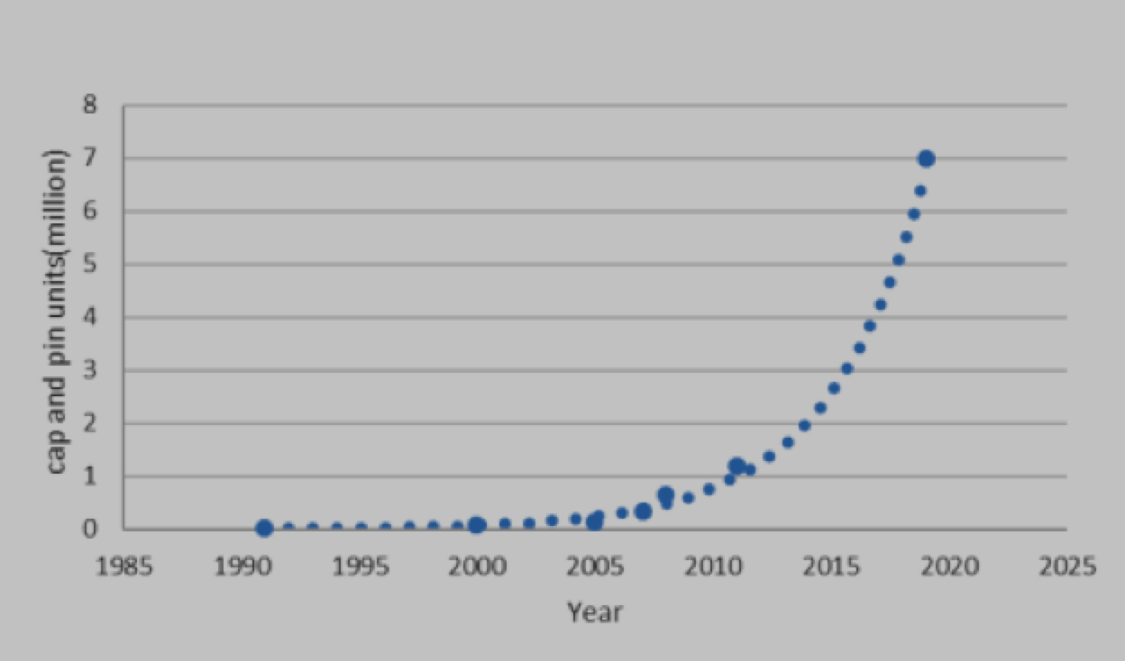
Factory-coated cap & pin insulators are increasingly being applied in harsh service environments due to perceived performance advantages. Recent estimates of the population of such insulators in service suggest exponential growth, with an estimate of more than 7 million coated cap & pin insulators in service as of 2019. This edited contribution to INMR by Alberto Pigini reviews current and expected future development of factory pre-coated glass and porcelain insulators.
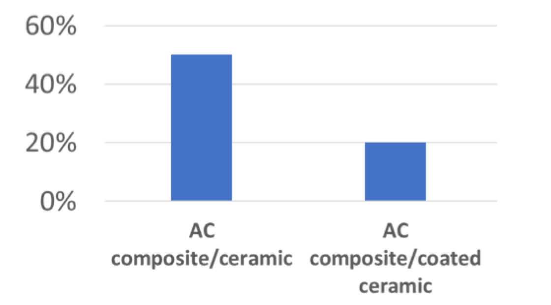
Comparison of lifecycle costs for the ‘composite insulator solution’ with respect to ceramic and RTV-coated ceramic solutions has been performed in one specific case and offers a qualitative indication of such differences. In spite of higher acquisition cost compared to composite insulators, the relative market gains being made by RTV-coated ceramic insulators is explained by expectations of much lower inspection costs, especially for glass insulators, as well as by greater confidence in mechanical performance.
CLICK TO ENLARGE
CLICK TO ENLARGE
RTV Silicone Material
The number of producers of RTV silicone insulator coatings has increased, corresponding to growth in the insulator market as well as in the rate of coating application. Today, this industry has increased to the extent that over 12 different suppliers are estimated to be competing worldwide.
During the early 1970s, first-generation formulations of RTV coatings were basically silicone sealants dissolved in solvent, where silicone was the component assuring the hydrophobic characteristics required. Later, silica powder (or quartz flour) was added for physical reinforcement. Subsequent generations of RTV HVIC products saw the silica powder replaced by metal hydrate fillers to improve performance under severe service stresses. Today, some of the most popular RTV coatings incorporate aluminum trihydrate (ATH), although other formulations available use either no filler or still rely mainly on silica powder. Experimental results demonstrate that some of these formulations allow reducing coating cost against only marginal decrease in overall performance. Moreover, advanced coating materials are now also available that feature super-hydrophobic, self-cleaning and ice-phobic properties. These coatings increase the range of possible outdoor applications to include reducing risk of flashover under icing combined with pollution.
[inline_ad_1]
Procedures to Apply RTV Silicone Coatings
The procedure used to apply RTV silicone coatings to ceramic insulators, whether glass or porcelain, is extremely important in assuring satisfactory long-term performance while avoiding problems such as premature peeling.
CLICK TO ENLARGE
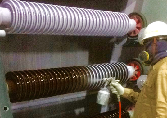
For example, pre-coated RTV insulators are now widely used in China, especially for UHV. There, automated dipping or spraying-on RTV coatings is carried out in a controlled wind-free, dust-free and constant temperature environment, with solvent recovery conditions as well. Compared with the traditional methods of spraying onto insulators at substations or on lines, these methods greatly reduce amounts of coating as well as emissions of volatile organic solvents.
CLICK TO ENLARGE
Among the most important elements to assure coating quality and uniformity is automated application. For example, more than 2 million of the estimated 7 million pre-coated insulators in-service worldwide have been pre-coated by means of automated controlled spraying. Of these, more than a million are installed on lines belonging to Italian TSO, Terna.
CLICK TO ENLARGE
Among the different possible coating procedures, spraying was selected in Italy with the goal of assuring better coating uniformity versus alternatives such as dipping. When the factory-coating process was first initiated, special attention was paid to qualification of the silicone compound formulation as well as to the need to assure cleanliness of the insulator surface prior to coating. Furthermore, assuring uniform thickness, proper control of the curing process and correct handling and packing all came to be recognized as key factors determining final coating quality.
[inline_ad_2]
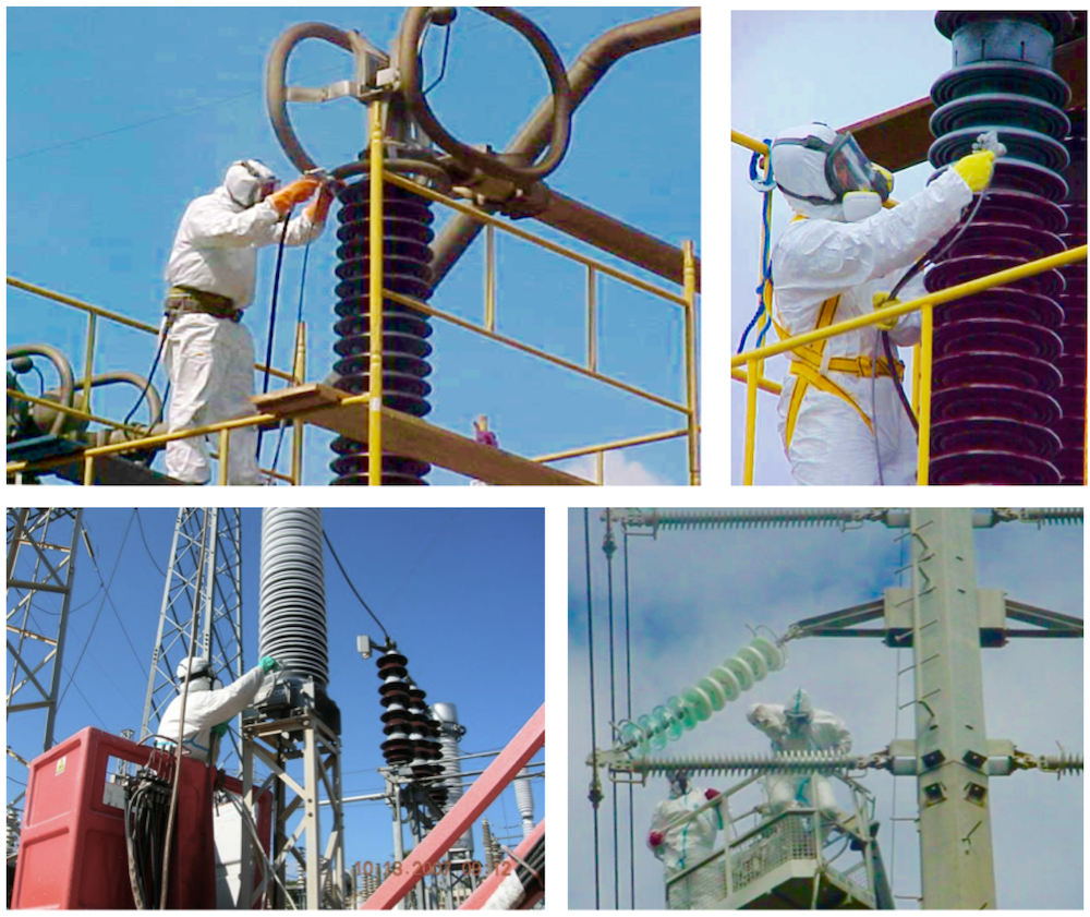
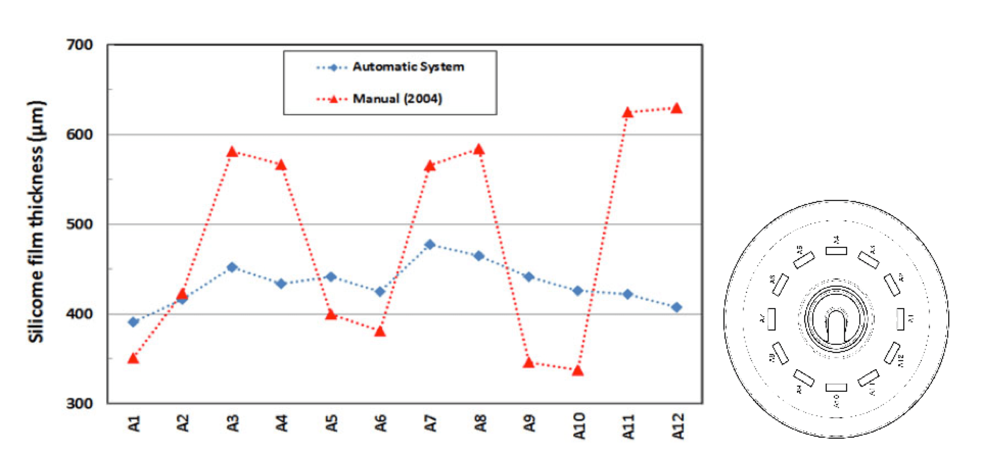
In the past, based on initial guidance by material suppliers, the coating process was typically performed manually by spraying. Coating quality and productivity were then greatly affected by operator skill and often insulators had to be re-worked due to non-compliance, e.g. coating not being homogeneous, difficult-to-reach areas not being sufficiently coated, etc. Moreover, this method required qualified personnel and offered low productivity along with waste factors of as much as 40%. All these issues impacted cost, safety and the environment. A lot of effort has since been devoted to automating the process as much as possible. For example, today’s modern systems see the spray phase managed by programmable logic controllers and carried out in controlled sealed areas. This not only assures more uniform coating thickness but also reduces environmental impact. Automation also significantly increases productivity, thereby reducing coating costs in addition to optimizing quality. These days, automated processes assure uniform coating thickness of ±20% all across an insulator.
CLICK TO ENLARGE
Need to identify optimal RTV coating thickness is also an important topic, with expert consensus that this should fall in the range 300 to 350 µm. For example, investigations at Istanbul Technical University in Turkey showed that increasing coating thickness up to 1 mm resulted in no apparent improvement in terms of suppressing leakage current during ageing tests. Moreover, sample temperatures due to leakage current actually increased with increased coating thickness, with possible negative impact on both performance and lifetime of the coating.
[inline_ad_3]
Design Criteria
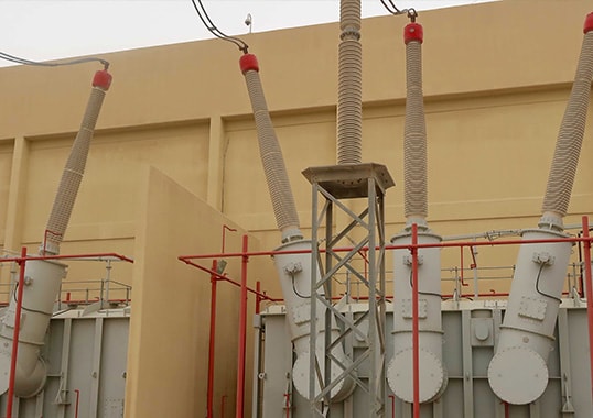
RTV coated insulators have their major niche in harsh service environments and decisions on their application should ideally be made at the design phase, taking into account specific environmental conditions. Special solutions, for example, could be necessary in very harsh environments such as the Middle East and North Africa as well as in the Gulf States. These areas are characterized by high UV, temperatures up to 56°C in summer with day to night fluctuations of as much as 25°C, early onset of dew and frequent windstorms that can have a sandblasting impact. Proper initial selection of insulators is critical in such situations. For example, while anti-fog profile cap & pin insulators are an excellent solution in marine environments such as Italy and Sweden, aerodynamic open profiles or porcelain long rods are often better suited to desert environments in order to limit pollution accumulation.
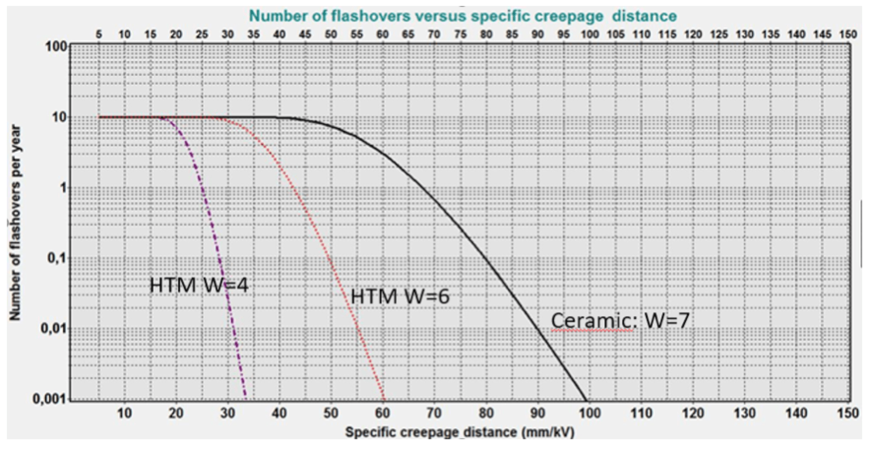
Moreover, insulators must always be correctly designed from a pollution point of view. To avoid risk of under or over design, a statistical design approach is recommended, especially in harsh environments. This approach is based on collecting accurate data about site pollution severity (in terms of SDD and NSDD), laboratory pollution tests on the insulators being selected and application of software to estimate risk of flashover or number of expected flashovers. One such application example is the harsh environment typical of coastal and gulf areas. A negligible number of flashovers (i.e. only 1 flashover per 100 years) were estimated assuming a USCD of 90 mm/kV for ceramic insulators and 55 mm/kV for coated insulators (conservatively taking into account ageing of coatings).
CLICK TO ENLARGE
Field Experience
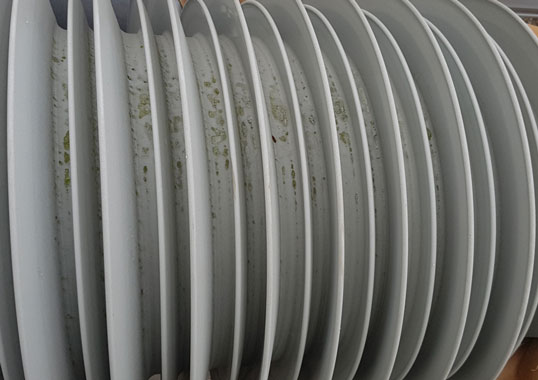
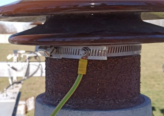
Italian TSO, Terna, has confirmed the satisfactory performance of more than a million pre-coated insulators installed in areas of harsh marine type pollution, with no reported flashovers after insulators were coated. One of the first concerns was uncertainty in regard to end-of-life of such coatings. In order to resolve such uncertainty, Terna performed annual sampling and inspection of coated strings. Based on this, an expected effective service life of more than 15 years was estimated for harsh environments. In fact, due to the outstanding performance in AC applications, Terna decided in 2008 to start application of coated insulators on DC lines as well. Line reliability improved immediately, with dramatic reduction in flashovers. Recently, for new high voltage stations in sites where contamination level is considered ‘very heavy’, Terna has decided to start application of pre-coated porcelain station posts.
Another example of successful application of RTV coatings was the 400 kV switchyard belonging to Coastal Gujarat Power Corporation’s 4000 MW Project in India. The design creepage for the 400 kV AC insulators, which ranged from 31 mm/kV to 33 mm/kV phase-to-phase (corresponding to USCD = 54 to 57 mm/kV), was found inadequate for ceramic insulators installed less than 2 km from the coast due to the challenging salt/desert environment. Insulators were site-coated in 2011 and this eliminated flashovers. Moreover, Swedish experience with insulators installed at selected sites with marine/industrial, heavy/very heavy pollution saw no adhesion problems, nor reports of erosion even after 19 years’ service. In contrast to uncoated porcelain insulators at these sites, no coated insulators experienced flashover and none showed indication of reaching the end of their service life.
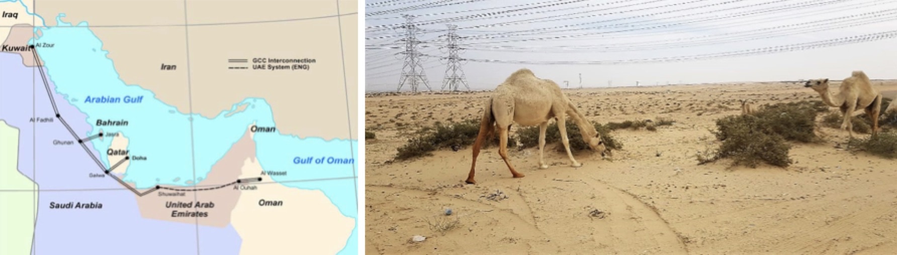
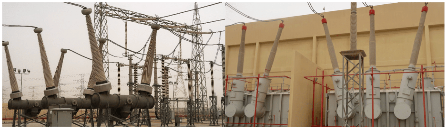
In Saudi Arabia and across the Gulf region, the service environment is particularly critical near the coast, with line and stations located there reaching ESDD and NSDD levels of 0.4 mg/cm2 and 1.6 mg/cm2 respectively. Following experience with composite insulators, the Saudi Electricity Company is presently installing composite insulators close to the coast but only on the eastern side of the country. On the western side, however, which has proven more critical for composite insulators, only coated porcelain long rods are being applied. As far as the GCCIA, all interconnecting lines and part the United Arab Emirates line are equipped with coated ceramic insulators having about a 50 mm/kV specific creepage distance line-to-line (corresponding a USCD of about 90 mm/kV). Pollution performance of these line insulators after about 10 years of service has been satisfactory. There were instances of local peeling and some glass insulators self-shattered but with no significant impact on service. Moreover, at the Al Fadhili Back-to-Back Converter Station all station posts and housings on the AC side are RTV coated porcelain, having much reduced creepage distance (about 33 mm/kV line-to-line, corresponding to a USCD of about 57 mm/kV).
While these insulators were washed annually in the past as a precaution, based on the good performance achieved a decision was made to wash less frequently (e.g. the last washing was performed three years ago). The RTV coating applied to station insulators about 10 years ago is performing well, without any reported flashovers and with coating under sheds remaining hydrophobic. As for the UAE interconnection, where composite insulators from two major manufacturers have been installed, several problems have been reported, such as splitting of the housing for one of these types and mechanical failures for the other. This experience prompted a review of past insulator policies in the UAE.
CLICK TO ENLARGE
CLICK TO ENLARGE
Opinion by experts is that all insulator types have their own specific niches. However, for extreme environments e.g. combinations of sea and desert sand with high salinity, hydrophobicity transfer materials, whether composite or RTV-coated insulators, may be required. These experts point out that good service performance can be expected of all insulator types that have been correctly designed (including optimal grading by corona rings for composite types) and also properly manufactured. When failures do occur, these should be carefully investigated to verify if they derive from inferior insulator quality or rather from inadequate design (e.g. too low USCD, inadequate shielding electrodes for composite types). It is not advisable to reach definite conclusions based solely on limited field experience, without rigorous supporting investigation.
Moreover, experience from test stations located in some of the world’s most severe environments, e.g. Koeberg in South Africa, Martigues in France and Al Fadhil in Saudi Arabia, helps engineers evaluate long-term performance of RTV coatings in general and compare the relative effectiveness of different coating materials in particular.
Need for Standardization
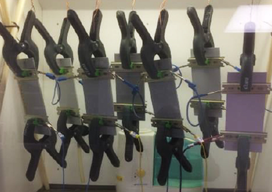
Suitability of tests available to evaluate coating quality is an important topic. Some in the industry have suggested using Fourier Transform Infrared Spectroscopy to ‘fingerprint’ different coating formulations while others mention assessing hydrophobicity transfer by measuring evolution of contact angles over time. Evaluation of hydrophobic properties by measurement of pollution layer resistance has also been proposed. Possibly, indication of expected service performance as well as comparison of different alternatives could be obtained using laboratory ageing tests based on experience and specifications by Terna – one of the world’s largest users of coatings. The relevant ageing test lasts 2000 hours, repeating weekly cycles, and aims to reproduce the ambient stresses, e.g. contamination, fog, rain, solar radiation and thermal influence, to which insulators are subjected during service. Choice of ambient and electrical stresses is made with the goal of accelerating the ageing process.
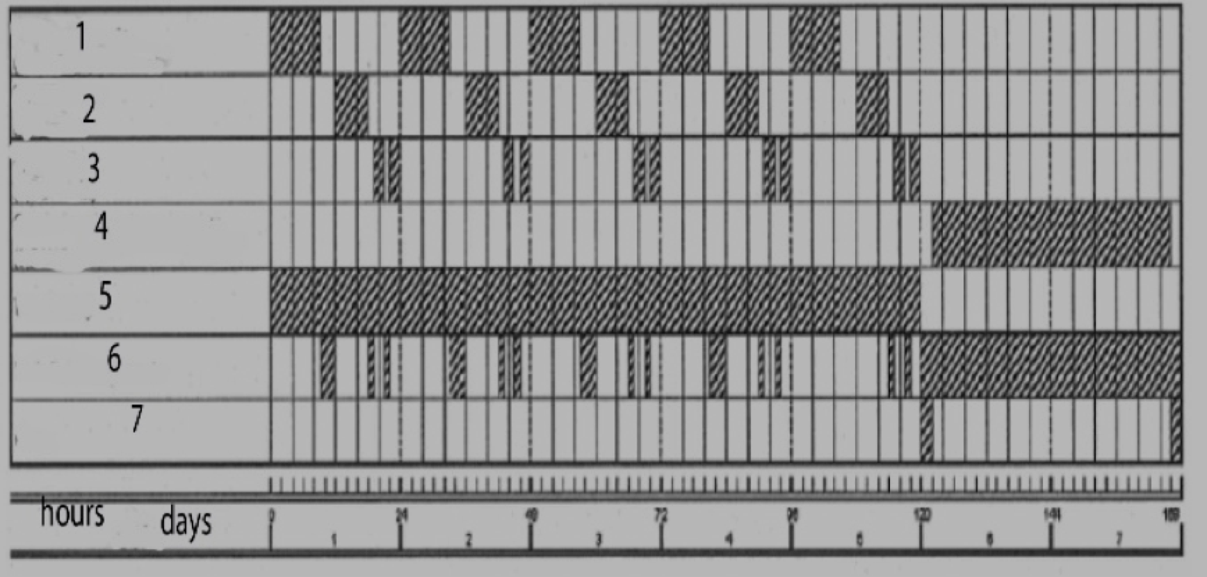
1: salt fog (40 kg/m3), 2: humidification (33 g/m3), 3: rain (1.5 mm/min), 4: solar radiation (1.5kW/m2), 5: voltage application, 6: drying period, 7: pause.
CLICK TO ENLARGE
Others in the industry suggest that nitric acid generated by partial arc discharges under pollution conditions will cause deterioration of the rubber surface. Since acid resistivity of the rubber can therefore be an important factor, a nitric acid immersion test to discriminate quality of different RTV silicone rubbers may prove useful. In general, the prevailing opinion of participants at this event was that utility design and maintenance engineers urgently need guidelines for RTV silicone coatings to help them deal with still unresolved questions. These include:
• most suitable RTV silicone formulation for harsh environments with particular reference to factors such as high UV, high temperature and the sandblasting effect of wind;
• minimum life expectancy;
• most efficient application technique;
• need for uniformity & optimal thickness;
• representative ageing and acceptance tests for harsh environments;
• most efficient procedure to characterize thickness, adhesion and surface hydrophobicity retention, recovery and transfer;
• identification of different coatings by ‘fingerprinting’.
Despite exponential market growth, IEC Standards to help guide product specification, as needed by both manufacturers and users, are still not available. While some guidelines are given in IEEE Standard1523 (IEEE Guide for the application, maintenance, and evaluation of Room-Temperature Vulcanizing (RTV), these are regarded as too generalized from the point of view of helping qualify a coating – especially in regard to tests to qualify long-term performance of a coating. Guidelines have also been proposed at some national levels (e.g. Chinese DL/T 627 – 2012: Standard “Room temperature vulcanized silicone rubber anti-pollution coating for insulators”) and summarize local experience as well. Available guidelines and various specifications already established by important users need to be analyzed, compared and implemented to arrive at some agreed international IEC document. As an important step forward, CIGRE has set up WG B2.69 “Coating for power network equipment. Chaired by Prof. Masoud Farzaneh, this group of experts collects and reviews available experience with the aim of arriving at guidelines from the CIGRE side – a good starting point for an IEC Standard. In parallel, to contribute to the activities of this WG, a voluntary R&D group was set up that will look to verify applicability of the ‘coated solution’ in harsh environments as well as for qualification testing to achieve standardization.