Once a decision is made to install a surge arrester of a particular type, design details when it comes to ideal mounting arrangement and how to deal with various line and earth lead issues can prove a challenge. These details can be made the more complex because a number of different considerations need to be addressed, including mechanical, electrical, surge and steady state issues.
This edited past contribution to INMR by arrester expert, Jonathan Woodworth, provided information and recommendations in this regard.
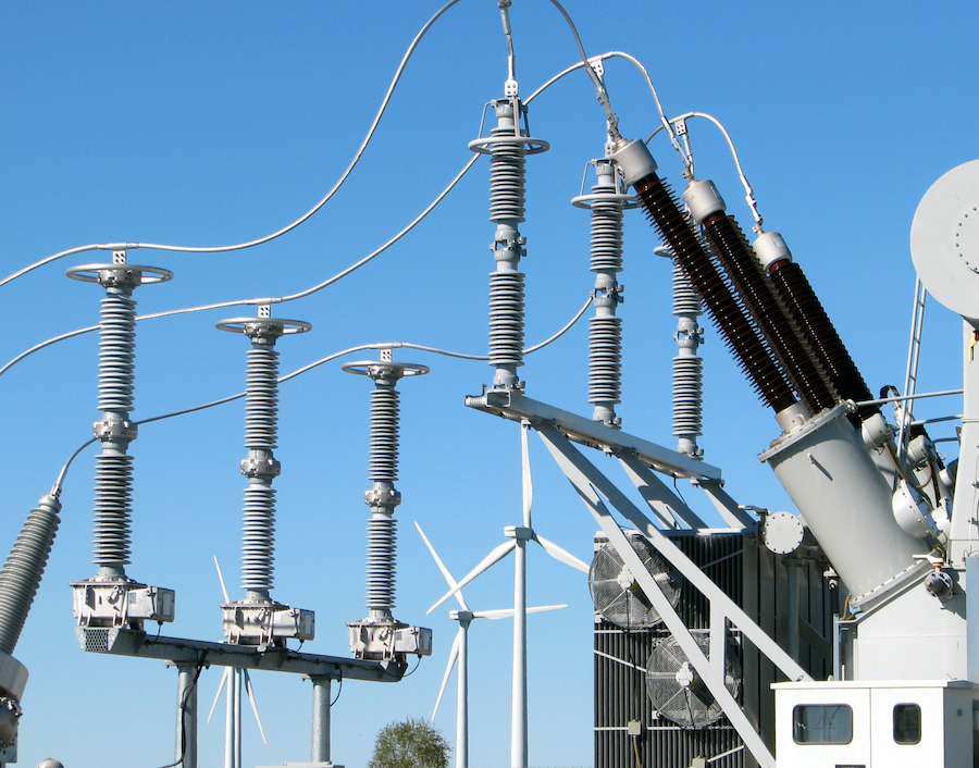
Substation Type Arrester Line Leads
In the case of arresters used at substations, the question of terminal conductor size is not based on ampacity as it is for other HV apparatus. This is because, at normal operating voltages, the arrester’s high impedance means that only microamps flow continuously through the conductors. Virtually any size of cable can withstand such a minimal requirement. Even under surge conditions, although current can become quite high (e.g. at times many kA), this is present for only a very short time, typically microseconds, and therefore any heating effect is negligible. The only time ampacity becomes the main criterion to determine size of a substation arrester conductor is when the unit becomes overloaded and short-circuit current from the system is flowing through the conductor as well as the arrester. If the cross-section is too small for such a condition, the connection and conductor could melt before the over current protection has cleared the fault. Should melting during such an end-of-life event be acceptable, selecting cable size based on this consideration is not necessary. However, if not acceptable, conductor cross-section must always be based on system short-circuit current magnitude and duration. Conductor size for a substation class arrester is therefore more determined by operating voltage. Since conductor diameter directly determines the corona inception voltage, the conductor’s minimum diameter on the arrester’s HV side is determined by this factor. Even though there is relatively no current flowing, the conductor must still meet corona requirements. Therefore, the HV conductor could be a four-bundled type at 500 kV levels while only a single conductor at 110 kV. In general, the mechanical requirements for the high voltage conductor of a substation arrester are only important in that it must be able to withstand the rigors of the environment. If the arrester will see service in a seismic zone, then the conductor must be flexible enough to withstand such events. Similarly, if the arrester is in an area with heavy snow loading, the conductor must be sized for this. Fortunately, conductor corona requirements and mechanical requirements do not conflict. Moreover, surge withstand plays no role in determining HV conductor size. Any conductor that can withstand seismic or snow loading forces can easily withstand magnetic forces during a surge.


In the case of substation arresters, size (diameter) of the conductor has very little effect on the unit’s ability to protect nearby insulation. The length of the conductor, however, can prove important in this regard. The rule here is that shorter is always better because inductance of the HV lead depends greatly on its length. For example, inductance of the line lead can add to the residual voltage of an arrester during fast rising surges such as those initiated by a back-flash and thereby reduce protection ratio.
Another important consideration related to lead length for arresters at substations is distance between the arrester and the protected equipment. This distance – called separation distance – should also be as short as possible. Time domain studies can be completed on the configuration to determine whether or not this will be an issue.
The material used for the HV conductor is not as relevant as it is for other substation equipment. Again, since there is no significant conduction through the lead, it does not have to be copper or aluminum. Of course, any alternative material (e.g. steel) must resist corrosion and be compatible with all connectors. Indeed, HV connectors on most arresters are not copper or brass but generally some form of corrosion proof steel. Weight of the line conductor may need to be considered if the arrester finds use as a bus or conductor support as well. When this is the case, the cantilever strength of the arrester needs to be carefully reviewed to ensure that the mechanical force on the arrester does not exceed its specification.
If grading rings are required on an arrester, their presence should not affect the conductor/arrester connection. Generally, the HV conductor is connected to the arrester directly from above. If that is not possible, it can enter the grading ring from almost any point.

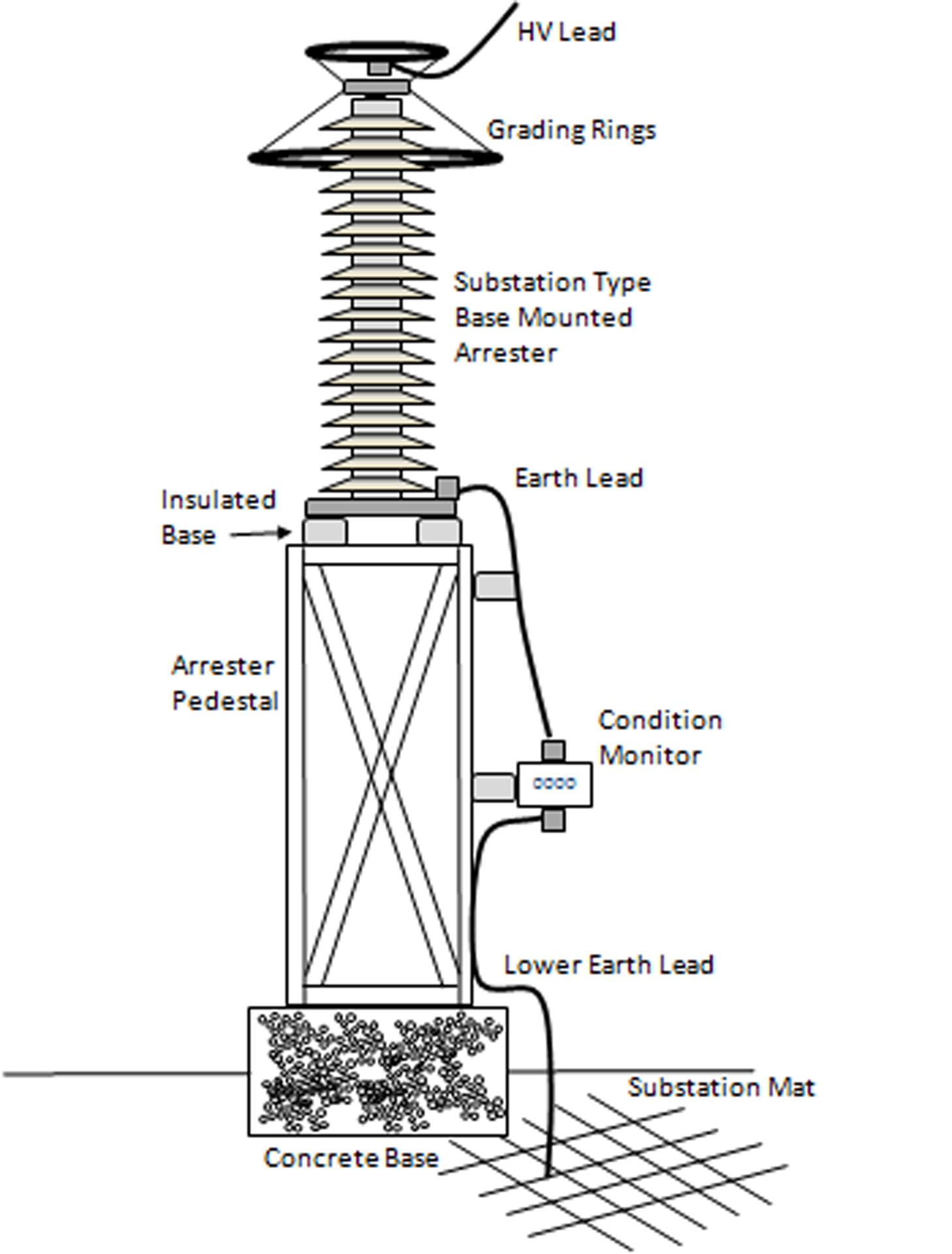
Base Mounted Substation Type Arrester Earth Leads
For base-mounted substation type arresters, the earth lead configuration depends primarily on whether it is mounted on the transformer frame or, alternatively, on a pedestal. Another consideration is whether or not there is a condition monitor. If such a monitor is used and the arrester is mounted on a pedestal, then the configuration will be similar to that shown in Figure 1. In this case, the earth lead is divided into upper and lower portions. The upper lead connects the arrester base and the input to the device and is insulated from earth so that all arrester current flows though the monitor. Note that the arrester’s base must also be insulated from earth with insulators. The upper lead can sometimes also be insulated, but this is not necessary as long as it is insulated from the earthed pedestal. The only time the voltage level on the upper earth lead exceeds a few volts is during a surge. In this case, the inductance of the lead along with the impedance of the condition monitor (if there is any) can result in several kV being present during the surge. The insulators then prevent surge current from conducting through the pedestal and bypassing the condition monitor. The lower earth lead connects the condition monitor and the earth mat of the substation. This conductor does not require insulation because if its voltage rises during a surge, it can arc to the pedestal with no negative effects.
Conductor size on the earth side of the arrester is governed primarily by mechanical robustness. At the least, it must be capable of withstanding the rigors of the local environment and any installation stresses. If it is convenient to use the same grounding conductor as used on other equipment, then that is all that needs to be considered. The conductivity of the conductor is also not important and therefore steel could be used in place of copper or aluminum. Forces on the earth conductor during a surge are not a relevant factor in determining size. Surge events are typically of such short duration that they do not generate sufficient magnetic forces to move a conductor that is larger than a few millimeters in diameter. If the earth conductor must remain undamaged during an arrester overload, then it should be very robust. By contrast, if it is acceptable for the earth lead to be damaged during arrester failure due to fault current, then size is again governed more by what is easy to install or conveniently available.
Since the steady state voltage on the earth conductor of a substation type arrester is near zero over its service life, corona is not a consideration.
The path taken by the earth conductor between the base of the arrester to ground mat should be as short as possible (for the same reasons the line lead should be short). The voltage rise across the lead during a surge due to inductance can be substantial and must be considered in the protection ratio between the arrester and the insulation it protects. It is inevitable that the earth lead will have bends that will increase it linear length. Should bends be required, the radius of each is not relevant to arrester performance. It is a common misconception that sharp bends in earth conductors of station type arresters are to be avoided. In fact, they have no impact on the arrester’s electrical characteristics. They may however have negative effects on conductor corrosion resistance and such concerns are the only reason to use sweeping bends in the earth leads of such an arrester.
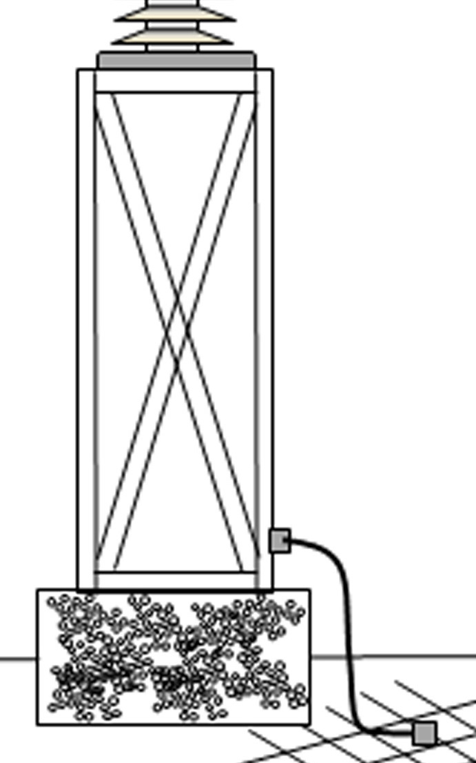
If an arrester condition monitor is not used and the arrester is mounted directly on the pedestal, a separate conductor along the pedestal (or transformer stand) is not necessary. The pedestal can then be used as an earth conductor for the arrester. It is usually undesirable for the concrete foundation to become the conductor. Therefore a conductor is used between the bottom of the pedestal and the earth mat (see Fig. 6).

Distribution Type Arrester Leads
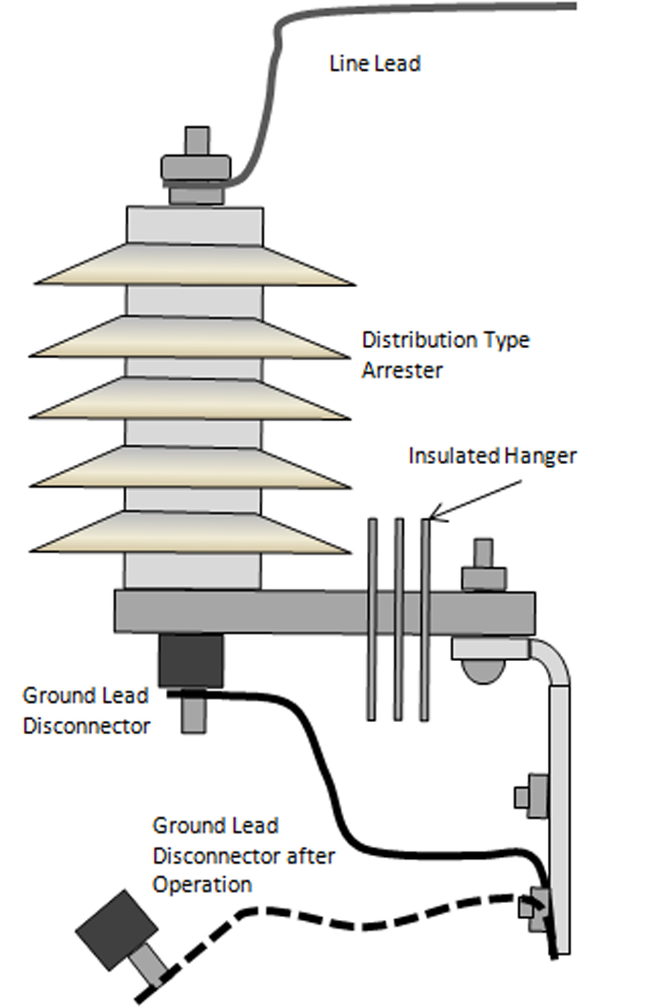
As shown in Fig. 7, distribution surge arresters can have very simple line and ground leads.
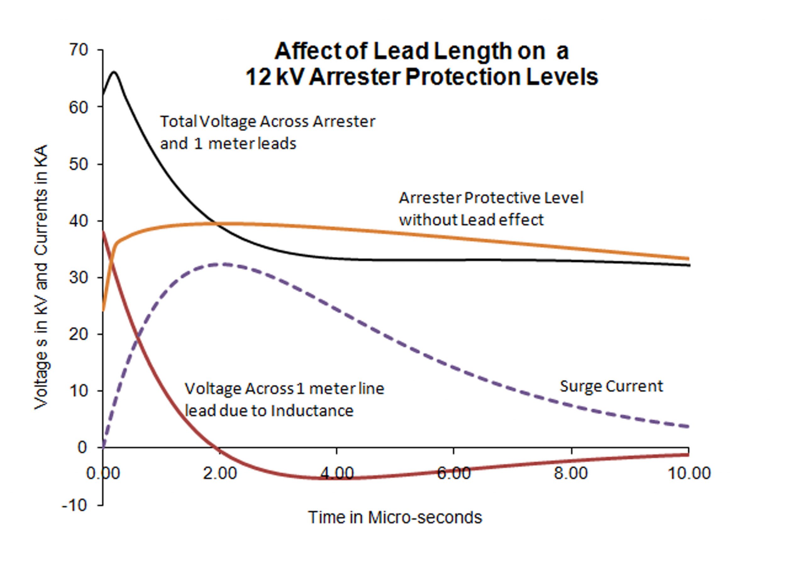
The most important factor in selecting the line lead of this type of arrester is length. As with all arresters, the inductance of the lead is a strong function of length but not diameter. The inductance of a lead can produce large voltage transients that must be calculated into the protection ratios of the arrester in the event of fast rising surges. If this type of arrester is mounted several meters from the protected insulation, the voltage appearing across the insulation can be 100% higher than the arrester’s residual voltage. In Fig. 8, it can be seen that one meter of lead length can add 25 kV to the protective level of an arrester over a 1 micro-second time frame.
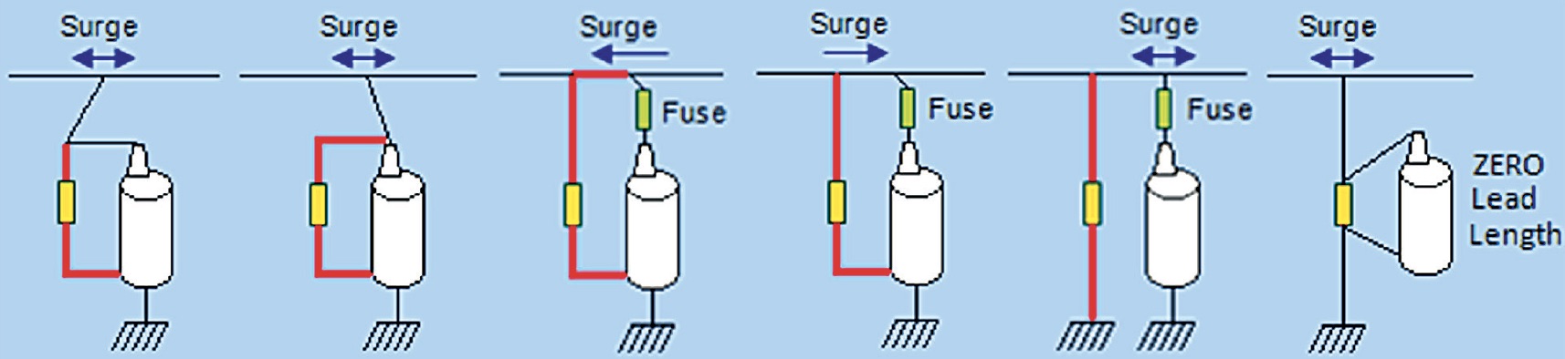
The method of calculating this added voltage is described in detail in arrester application guides IEC 60099-5 and IEEE C62.22. Very often the determination of relevant lead length is difficult – in other words, what lead is or is not to be counted in the calculation. The general rule to determine what is relevant lead length in any configuration is: any lead that is in parallel electrically with the protected equipment and carries surge current is relevant in terms of length. Fig. 9 provides examples of relevant lead lengths.
The diameter of distribution type arrester line and ground leads are again dependent on desired physical strength. Diameter does not greatly affect inductance and therefore has little impact on electrical performance. The ampacity of the line lead is only relevant if the down conductor is part of the system load current (as shown in the first example in Fig. 9). AWG #4-#8 is quite commonly used on these type of arresters for both line and ground leads.
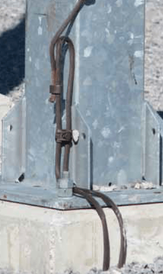
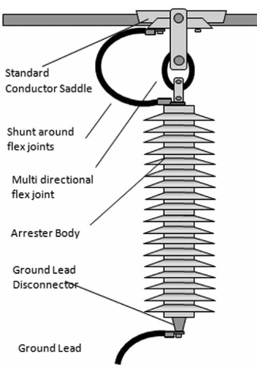
Since this type of arrester is often quite short, wildlife initiated outages due to leads that are too close to earth can become a concern. When configuring the leads, it is advisable to adjust them for maximum clearance. If the lead is insulated, the insulation withstand level must be at least equal to the arrester’s voltage rating. If possible, the lead should be configured directly out of the top of the arrester and an appropriate wildlife protective device be used. Wind and vibration are minimum considerations on leads in these applications. If the arrester is equipped with a ground lead disconnector (GLD) as shown in Fig. 7, it is important that the ground lead not be tightly secured to the cross arm or other components until it is 10-15 cm away from the GLD. This ensures that the GLD can properly isolate the bottom of the arrester from earth when it operates (also shown in Fig. 7).
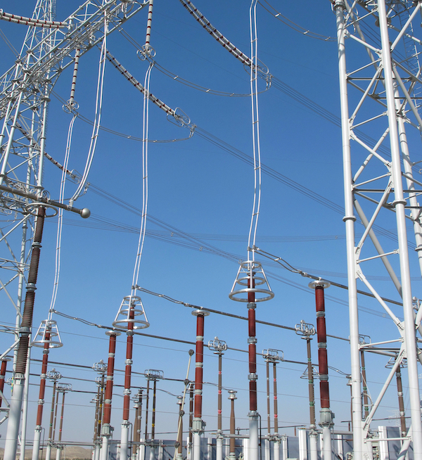
Non-Gapped Line Arrester Leads
The line and ground leads of non-gapped line arresters (NGLA) have quite different requirements than either station or distribution type arresters. Here, field experience has demonstrated that the robustness of the lead is very important. In particular, the vibration and bending withstand capabilities of the connectors need to be much higher, due to the application environment which experiences the same wind and vibration as other line hardware. Of course, this is less critical at distribution system voltage where the structures are shorter and becomes more critical as system voltage and tower height increase.
One successful method to mitigate the effect of wind on the ground lead of such an arrester is to string it along with a heavy chain that dampens any swing and motion. Another significant difference between this arrester application and others is that lead length is not important. Since the only purpose of line arresters is to protect the line insulation from flashover, the protection levels of the arrester and leads need not be as low as for arresters protecting sensitive equipment such as transformers. Still, if exceptionally long leads are needed for an installation, it might be prudent to carry out an EMPT type study of the system. While at lower voltages corona is not usually an issue, above 200 kV this needs to be considered. Another unique characteristic of this type of arrester is that the disconnector is not always mounted on the earth end of the unit. In some installations, the disconnector is connected to the high voltage end and is energized throughout its life. In these cases, the disconnector and the lead connected to it both need to be corona and RIV free so not do disturb radio or TV reception in the area.

Arresters Applied on Overhead-Underground Transition Towers
Arresters applied at transmission towers above 69 kV to protect underground cable are similar in characteristics to station arresters. In this application, length of the HV lead and that of the ground lead are important. It is also desirable to mount the arrester as close to the line termination as possible.
The rationale for using an arrester in this application is that any surge entering the underground circuit will likely double in amplitude if it meets an open point in the circuit. If a surge is allowed to double in the underground circuit, the solid dielectric insulation might be stressed beyond its capacity. Underground cable is not self-healing (as are air insulators) and failure to protect this type of circuit has numerous negative ramifications.
Lead size in such an application needs to have adequate diameter to avoid corona issues. Moreover, they also need to be of adequate size to resist wind and vibration stresses. If the lead conductor also carries load current (as shown in Fig. 14), then it must also be sized for the correct ampacity. If the arrester lead is not part of the load current path, then ampacity is not an issue. If the support structure is conductive in this application, then it is not necessary to have a separate ground lead as long as the termination ground is well connected to the structure.

Conclusions
As seen from the examples discussed above, there is no universally best solution on how to configure the line and ground leads of arresters. Rather, optimal configuration depends on application and arrester type. It is also wise to keep in mind that should there remain doubt on how best to configure the leads for an arrester application, the manufacturer will be a valuable resource to consider.
[inline_ad_block]