On-going development of overhead power infrastructure faces key challenges these days from the perspectives of cost as well as objections by a public that has grown wary of transmission lines. While cable may offer a solution in terms of visual impact, it comes with a significant construction cost premium. Maintenance and repair is also more expensive and time consuming.
Expanding the power transfer capacity of existing overhead lines is one solution and involves options such as re-conductoring or application of flexible AC transmission systems. Upgrading lines on existing corridors is also an option and can be achieved by modifying towers to handle higher voltages or by moving from single circuit to double circuit lines. Still, rebuilding lines on existing routes also requires planning consent, which depends on public approval – just as for new lines. In both cases, making towers as low and unobtrusive as possible helps reduce visual impact and maximize acceptance by affected communities.
Based on these considerations, much research has been devoted to finding tower designs that utilize composite cross-arms to replace insulators as well as traditional steel cross-arms. Such a single insulating structure could offer benefits, especially for application on lines in urbanized areas. However, an insulating cross-arm solution is neither traditional insulator nor traditional cross-arm. That means suitable testing and evaluation must be carefully considered.
This past article contributed to INMR by Prof. Simon Rowland, Ian Cotton and David Chambers of the University of Manchester in the U.K., described one such program that focused on the practical application of such cross-arms on lattice transmission towers.

Tower Configurations & Composite Cross-Arms
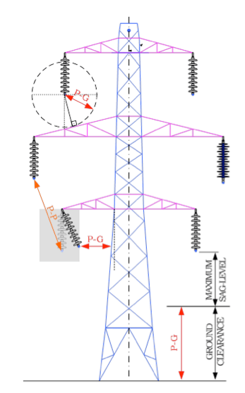
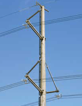
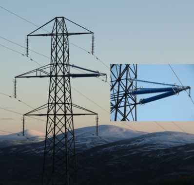
A typical twin circuit tower of the type used in the United Kingdom and elsewhere is illustrated in Fig. 1. Here, tower height is effectively determined by factors such as statutory ground clearances, conductor sag, insulator length, conductor-to-conductor separation, conductor-to-tower clearance and lightning shielding requirements. Depending on system voltage, span length, conductor and service environment, some of these factors become more important than others. In addition, possible blowout conditions (i.e. when an insulator assembly breaches the required air gap from the tower) contribute to determining tower width and also when making for conductor-to-tower calculations.
CLICK TO ENLARGE
CLICK TO ENLARGE
Among the key benefits of composite cross-arms is that insulator swing under windy conditions is reduced to a minimum and instead determined by metal clamping assemblies. There is also no requirement for additional tower height to accommodate the length of the insulator string itself. Therefore using composite insulating cross-arms can effectively raise heights of conductors by this same distance, i.e. about 4 m in the case of a 400 kV line. Basically, such a solution can:
1. resolve ground clearance problems on existing lines;
2. allow greater sag on existing or new conductors, critical to improving power transfer capacity since it enables conductors to run at highest rated temperatures while still not infringing ground clearances;
3. facilitate voltage upgrading due to improved clearances from towers, especially since risk of blow out is mitigated;
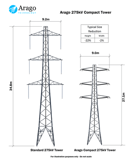
4. permit more compact towers with smaller foundations and therefore reduced costs (see Fig. 3).
CLICK TO ENLARGE

Mechanical Requirements
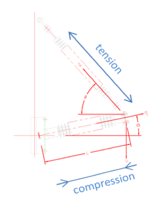
In normal operation, the higher elements of a cross-arm are in tension and the lower elements in compression (as in Fig. 4). It has also been noted by experts that the fundamental limit to application of such a cross-arm is the compressive strength of its lower member. If this limit is exceeded, the cross-arm will buckle. Typically the most extreme and limiting situation for design is under broken wire conditions, in which case high asymmetric stresses are experienced in the cross-arm. This is less of a problem for cross-arms designed to be able swing to the side, as seen on compact lines supported by steel poles. Composite insulator cross-arms have therefore become popular for such applications. Still, even in this case, insulators may need to be ‘doubled-up’ to provide sufficient compressive strength (as in Fig. 5). This is because traditional composite insulators are not able to provide sufficient compressive strength since their diameters would have to increase to the point that they become too heavy or too costly to produce. In cases of steep terrain, galloping or ice shedding, the circumstances whereby a cross-arm is exposed to uplift also has to be considered in power line design.
CLICK TO ENLARGE
CLICK TO ENLARGE
Electrical Requirements
The electrical requirements of insulating cross-arms are essentially equivalent to those of the insulators they are intended to replace, i.e. long, reliable service life under stresses including lightning and switching impulse withstand. Avoidance of high power frequency leakage current and flashover events are also basic system requirements.

Concept Realization
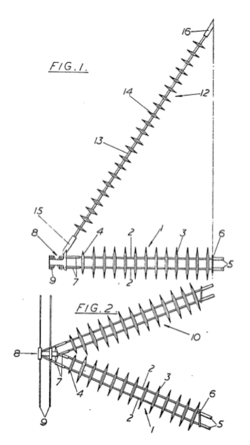
The motivation behind composite cross-arms has existed for many years although early designs to replace lattice structures were not deemed practical due to limitations in insulating materials and systems of the day. Indeed, as far back as 1964 it was suggested that the underlying problem of buckling under compression could be solved by using resin rods rigidly bonded by cross-members (as in Fig. 6). The practicality of this solution however was limited by its construction and by the fact that high performance polymers such as silicone rubber were not available for the sheaths and sheds.
CLICK TO ENLARGE
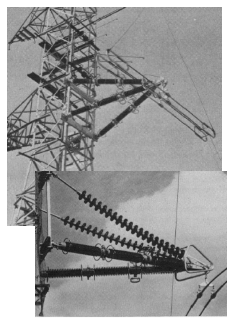
In 1971, a fully insulating cross-arm was developed for a lattice tower based on ceramic technology (Fig. 7) but its weight would have required especially robust lattice towers and mechanical considerations also made it impractical.
CLICK TO ENLARGE

Testing & Trials of New Design
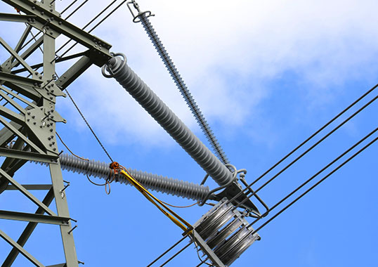
A new design of cross-arm capable of being deployed on 132 kV, 275 kV and 400 kV lattice towers is shown in Fig. 8. The cross-arm in this case was installed on four consecutive towers and replaced the middle cross-arm of a redundant line. Its basic insulating elements are fabricated from standard pultruded fibreglass and silicone rubber, but of a unique and proprietary construction.
CLICK TO ENLARGE
Mechanical Testing & Field Trials
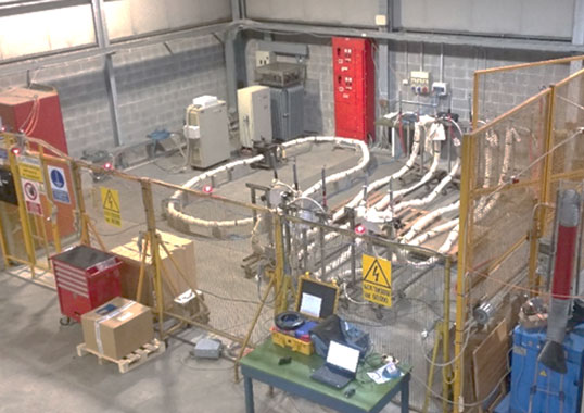
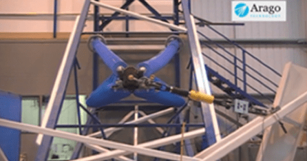
Prior to installation, the cross-arm was tested mechanically (without energization) to verify design techniques. In particular, broken wire testing (i.e. highly asymmetric loads as in Fig. 9) as well as ultimate tensile tests were found to satisfy design predictions and confirmed that the cross-arms could indeed withstand normal service requirements.
Over the two-year trial, real-time monitoring took place, including video imaging during prolonged snowy periods. Wind speeds of over 100 miles per hour (160 km/h) were also recorded. Together, these offered excellent data on the reliability of the cross-arm such that it was decided to proceed next to a live trial.
CLICK TO ENLARGE
CLICK TO ENLARGE
Electrical Testing & Field Trials
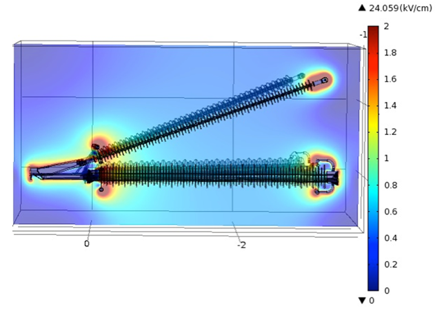
Electrical modelling using finite element analysis was performed in order to generate full 3-D models of the unit’s complex geometries at the precisions required. In particular, consideration was given to controlling field stress at the high-voltage end of the cross-arm.
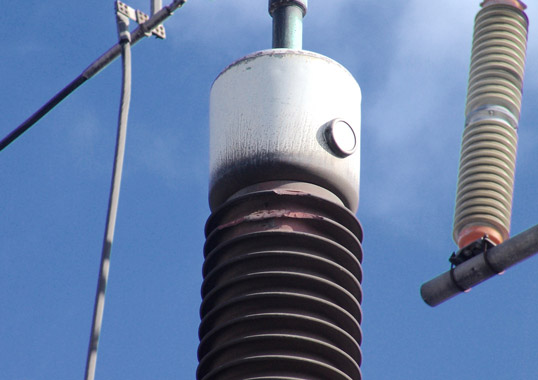
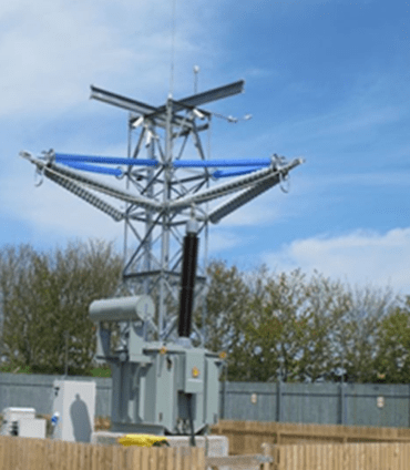
Standard laboratory tests for insulation systems, including impulse and wet withstand, were completed prior to installation on a live system. This trial, energized at 400 kV system voltage, saw two perpendicular cross-arms mounted on a specially constructed lattice tower. The cross-arms were placed perpendicular to one another to determine if wind direction played any role in electrical performance.
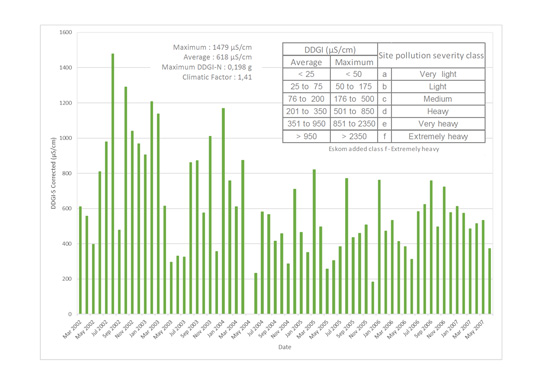
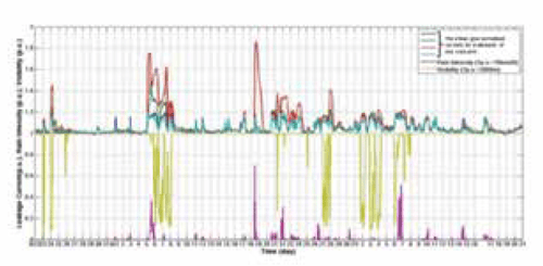
Leakage current to ground on each of the four insulating elements of all cross-arms was continuously monitored, allowing all to be compared. This enabled electrical performance of the four traditional tension members to be directly compared with that of the four compression members. In addition, the site was monitored using video cameras that also provided close-ups of all surfaces. A weather station at the top of the structure allowed real time monitoring of wind speed and direction, RH, precipitation, visibility and solar radiation, i.e. all environmental factors that could affect performance.
CLICK TO ENLARGE

Conclusions
Composite insulating cross-arms have been developed as part of a multi-year research and test program. These are intended to replace steel cross-arms and suspended vertical insulator strings on traditional lattice towers, thereby enabling conductors to be attached directly to the cross-arm.
Major potential benefits to transmission system operators on existing lines include:
• retro-fitting towers, with no change in tower dimensions or profile, while allowing up to 150% more capacity due to increased ground and tower clearances;
• increasing ground clearance so as to overcome any possible local infringement issues;
• greater current carrying capacity of conductors due to increased allowable sag;
• upgrading the voltage of exiting towers, for example taking 132 kV towers to 275 kV.
In the case of new lines, there would also be benefits of:
• cost savings through reduced time for obtaining planning approvals and also due to smaller structures and foundations;
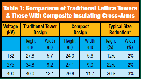
• reductions in tower heights (see Table 1).
CLICK TO ENLARGE