[inline_ad_block]
I recently participated at a conference that dealt with best practice for extra high voltage overhead lines. It was good to work with old friends and also meet other experts as we organized the program. We applauded the recent election of keynote speaker, Rob Stephen of Eskom, as new CIGRE President and also had a friendly competition to make sure that all breakout sessions (e.g. in lightning, insulation coordination, unmanned airborne vehicles, noise and mechanical aspects) were well attended. Organizers of the event coached speakers to talk less in order to allow more insight into specific problems experienced by those in attendance.
One common theme was: “those who measure, know”. This column in Q2, 2016, for example, covered high shielding failure rates observed on UHV lines in Japan and we were able to learn more about the measurement campaign behind this. Incidentally, experience from South Africa confirms that measuring and improving grounding at 400 kV remains good advice to reduce back-flashovers.
On the way home, a travel delay allowed me to catch up with a colleague who is expanding a line inspection service that combines video and high-resolution photos with images from infrared and ultraviolet cameras. We talked about how this allows four different classifications for assets such as non-ceramic insulators. A polymeric insulator or transmission line surge arrester (TLSA) that presents a heat rise clearly has problems. If it also has an ultraviolet signature, these may be severe. And if there is visible damage as well it is probably time to remove the unit from service. But an experienced inspector is still needed to distinguish false positives from real problems. We also discussed the role of audible noise that is difficult to assess from a noisy helicopter and mused over the convenience of possibly adding wideband electromagnetic noise tracking to further refine the classification.
As we spent the time trying to resolve the world’s transmission line problems, we found that our laptops held complementary photographs. Images on mine taken in May 2011 showed the right-of-way of the I2P transmission line in northern Saskatchewan, Canada. This line was constructed in the 90s and the ‘P’ refers to ‘Points North’. It has no overhead ground wires (OHGW) and is equipped instead with a continuous counterpoise along two of the four guy wires at each Y-shaped steel pole. I came to know this line from a field campaign to measure whether the counterpoise would be effective for grounding a second 230 kV line proposed to be built along the same right-of-way. We were surprised to discover that, at one tower, an insulated cable laid on the rock had lower surge impedance than the counterpoise itself. The equivalent height of the counterpoise, if suspended above perfect ground, worked out to about 1 m at this location. At other points, forest fires had melted aluminum connectors that isolated the steel counterpoise from guy wires and rock anchors but left them otherwise intact.
With such tests indicating that grounding would be difficult at many locations, the design team for this Island Falls to Key Lake (I1K) line considered alternatives to protect the CA$ 330 million investment. Line construction cost was influenced by the fact that access to the right-of-way had to be by helicopter and indeed 45 helicopters supported construction with some 30,000 hours of total flying time. Optical fibres were fitted into the OPGW. However, my colleague pointed out a minor detail that could be a world first and is certainly best practice.
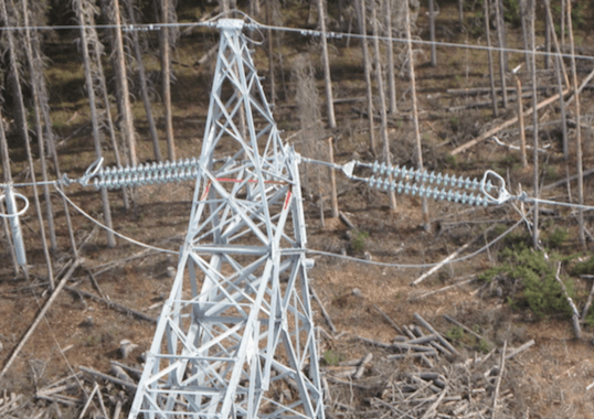
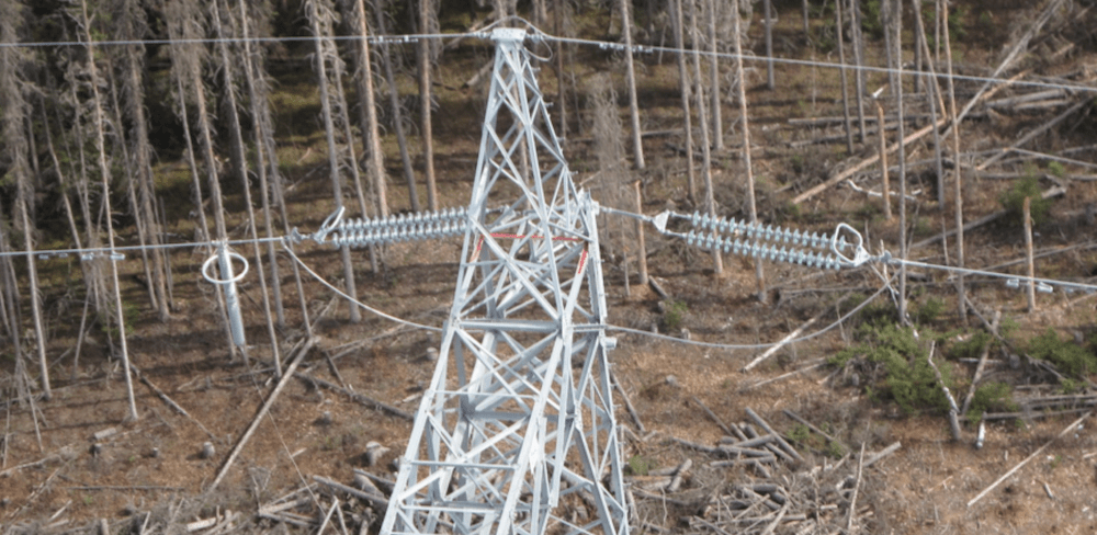
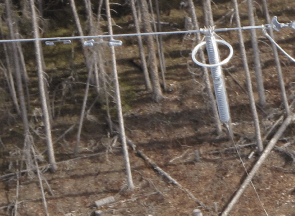
In Saskatchewan, they say it rarely gets colder than -43°C and this is supported by climate data. Treatment of Aeolian vibration with dampers is a priority when dealing with high line tensions at such temperatures. The dampers are pairs of weights connected with a wire. A single damper on either side of a suspension clamp is usually sufficient to protect each span. On the new I1K line, however, the OHGW have four rather than the usual two dampers while the phase conductors have three.
CLICK TO ENLARGE
CLICK TO ENLARGE
Photos also show that the TLSA, suspended from the conductor on the left, has a large corona ring above and below a long ground lead connected to the tower. Previous columns reviewed mechanical issues that could arise when suspending such a heavy TLSA from phase conductors. Most relate to retrofit or upgrade projects where the arrester is placed between the existing insulator clamp and the Aeolian vibration damper. What’s exciting about the arrester treatment on this particular line is that dampers seem to be placed in positions that would also effectively protect the conductor under the TLSA clamp. Someone seems to have informed the damper manufacturer during the design process about the use of a TLSA and the placement was adjusted on the side with the unit. As further insurance, armor rods were placed between the TLSA clamp and the conductor.
Photo credit: E. Petrache, Kinectrics.
CLICK TO ENLARGE
The October 2016 issue of online journal, CIGRE Science and Engineering,provided technical details and mitigation recommendations on this topic. In preparing the article, there were many examples of ‘don’t do this or that’. It is therefore now a positive contribution to look at this line and say: ‘do this instead’.
Dr. William A. Chisholm