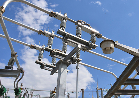
The metal oxide surge arrester (MOSA) is a comparatively inexpensive component within a modern power system. Typically, it is specified, purchased and installed but later overlooked when planning condition monitoring of assets in a substation.
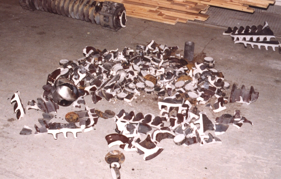
However, an arrester is one of the key components for protection of expensive equipment such as power transformers and HV cables. Moreover, explosive failure involving porcelain-housed arresters presents an unacceptable risk not only for maintenance staff at the station but also for nearby apparatus. In addition, ageing arresters mean reduced overvoltage protection, especially for older equipment and this can result in accelerated degradation of their insulation systems. Indeed, it is far more cost effective to replace an arrester before it fails than to deal with any resulting unplanned outage.
This edited past contribution to INMR by experts at Doble TransiNor in Norway reviewed condition assessment of arresters using leakage current to diagnose and prevent incipient failures.
In-Service Degradation of MOSAs
Surge arresters at substations are exposed to a variety of stress factors originating both from the network and from the service environment that can then cause premature ageing or even damage to varistor blocks. The main types of such degradation can be classified as either:
• Degradation of insulation properties; or
• Degradation of protective characteristics
Several mechanisms can cause degradation or, in the worst case, failure of MOSAs:
1. Sealing defects leading to moisture ingress;
2. Surface discharges due to contamination;
3. Overloading due to temporary or transient overvoltages;
4. Long-term ageing at normal service voltages, e.g. when the specification is inappropriate for actual system voltage and overvoltage stress;
5. Internal partial discharges.
Overloading typically occurs after fault situations with high temporary overvoltages in the network. If the rated voltage of the arrester has been selected too low, risk increases that it could become overloaded – even at a temporary overvoltage it should have been dimensioned to withstand. One consequence of degradation of the arrester’s protective characteristic is an increase over time in the resistive component of the continuous leakage current flowing through it. This in turn will cause increased power losses and hence raise the temperature of the metal oxide (ZnO) blocks. At some point, resistive leakage current reaches a critical limit where the energy accumulated in the blocks exceeds the arrester’s capability (i.e. the energy it can dissipate to the surroundings). The arrester will then become thermally unstable, often referred to as ‘thermal runaway’, and fail.

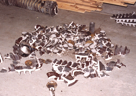
Modes of Failure
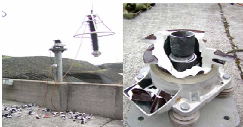
1. An arrester equipped with a porcelain housing can in the worst case explode and cause severe consequential damage. If the arrester has a polymeric housing, the risk of heavy, sharp objects being scattered is far lower;
2. The arrester could trigger an earth fault (e.g. due to internal flashover). Such an arrester can at times be difficult to identify;
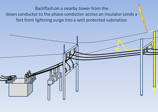
3. Aged or overloaded arresters offer reduced protection against overvoltages, (e.g. during severe transient overvoltages due to multiple lightning strokes or high-energy temporary overvoltages). The arrester can fail before it has suppressed the overvoltage, meaning that the apparatus being protected will be damaged.
Methods to Monitor Degradation
Several methods and indicators are currently used for in-service monitoring, diagnosis and assessment of MOSAs. These vary both in handling complexity and level of information provided. The two main approaches are on-line and off-line measurements. Off-line measurements provide a testing environment with full control over parameters that affect reliable and repeatable measurements. This approach requires de-energizing the arrester and using a portable voltage source or, alternatively, taking the arrester to a laboratory. By contrast, on-line measurements are done on a temporary or continuous basis and use portable instruments as well as permanently installed devices. Such methods have the advantage of providing condition assessment data without need to remove the arrester from service. A combined approach involving additional off-line tests could then be used to verify conclusions from on-line measurements should there be doubts. Among the most common in-service methods are:
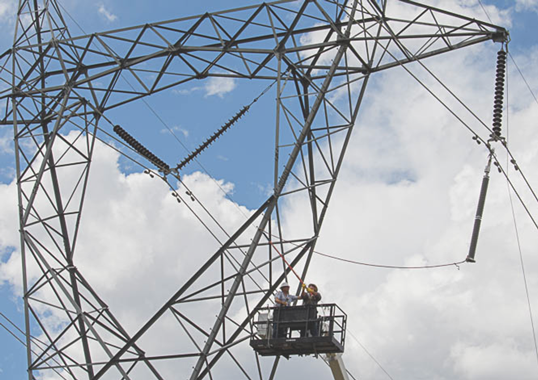
1. Visual Inspection
This is a common and even valuable approach to locate any external abnormalities. For example, experienced crews can visually detect deterioration of seals at end fittings, damage to the external housing or evidence of high levels of surface contamination. Still, this gives little or no information about the arrester’s internal condition and ideally should be combined with other methods so as to obtain a reliable, complete assessment of condition.
2. Surge Counters (with or without mA meters)
These provide measurements of total leakage current but, while frequently installed on MOSAs, are of little practical value as a diagnostic tool to assess real condition of the arrester.
3. Temperature Measurement
Infrared thermo-vision inspection of arresters is a frequently used multipurpose substation maintenance technique, including for arresters. Indeed, experience shows that thermal imaging can be effectively used to track surge arrester degradation. However, such measurements are indicative only to the extent that they are sensitive enough to identify increased block temperature by detecting its impact on the surface of the arrester housing.
4. Measuring Leakage Current
This is the most commonly used diagnostic method for arrester condition assessment and a variety of on-line and off-line methods are available. In the field, this parameter is normally measured only at the earthed end and the arrester must therefore be equipped with insulated base and leads separated from earth potential.
The method with indirect determination of the resistive leakage current component by means of third harmonic analysis with compensation for voltage harmonics (THRC) is regarded as one of the best available for on-site, in-service information and also diagnostic efficiency.
Electrical Properties & Determination of THRC
Current-Voltage Characteristics
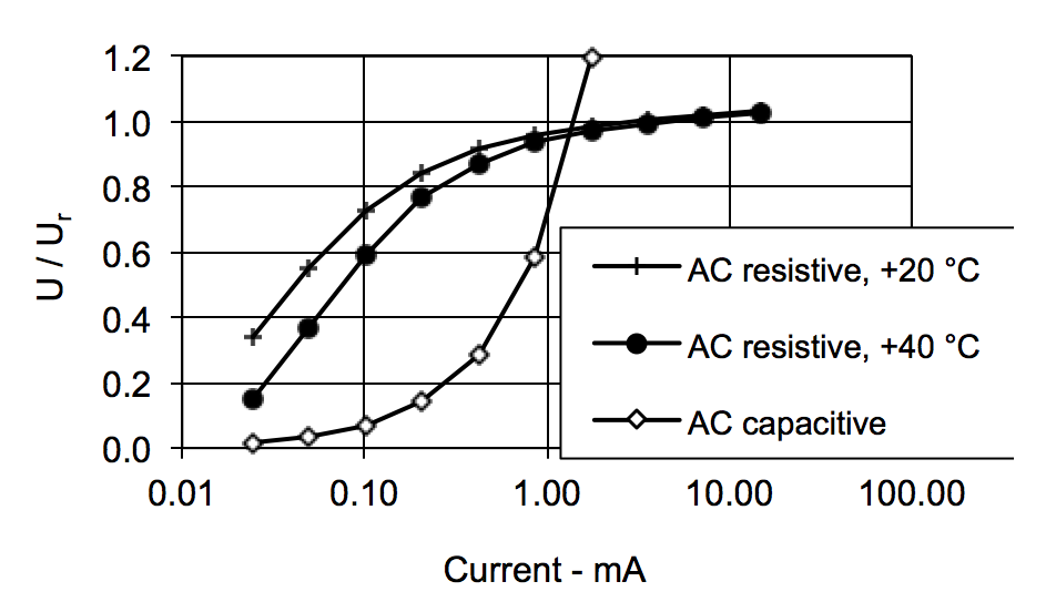
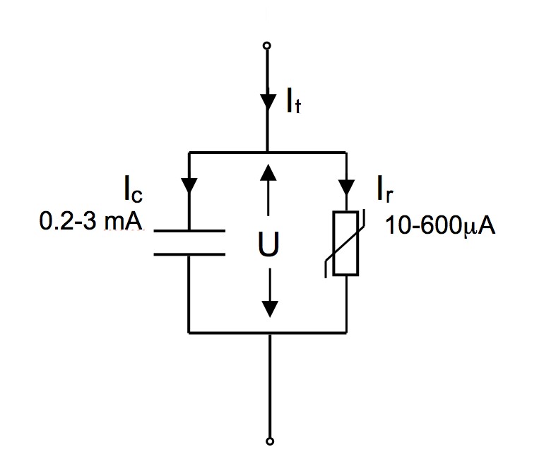
Under normal service conditions, the arrester carries a small but continuous leakage current, typically in the range of 0.2 to 3 mA. This current is dominated by its capacitive component, while the resistive component might be in the range of only 5 to 20% of this amount. Moreover, the resistive component is temperature and voltage dependent, as seen from a typical current-voltage characteristic curve shown in Fig 1. Therefore, the ZnO elements of the MOSA can be represented by the equivalent electric circuit shown in Fig. 2, where equivalent resistance is non-linear. The typical operating voltage, U (phase-to-ground), for a MOSA is in the range of 50 to 80% of its rated voltage, Ur. (Definitions might vary depending on whether ANSI/IEEE C62.11 or IEC 99-4 is used).
Leakage Current
The current-voltage characteristic shown in Fig. 1 is representative for a MOSA when stressed by a pure sinusoidal voltage (fundamental frequency component only). Total leakage current flowing through the ZnO blocks can then be divided into its:
• fundamental capacitive component;
• fundamental resistive component;
• the 3rd harmonic resistive current component (due to the non-linear resistance of the ZnO elements and said to be generated by the arrester itself).
The resistive components (i.e. the 1st and 3rd) at any specific voltage and temperature will reflect the current-voltage operating point characteristic of an arrester and change during ageing. Both these components can therefore be used as a measure of the arrester’s operating condition. However, for field measurements in three-phase configurations, the best practical solution is to determine the 3rd harmonic component of the resistive current. The leakage current for any particular arrester can vary across a wide range due to: harmonic content of the system voltage; actual temperature of the ZnO elements caused by both ambient conditions and any discharges; and operating voltage.

Effects of Harmonic Content
The presence of harmonics in the operating voltage can generate a 3rd harmonic capacitive component in addition to the 3rd harmonic resistive component. These two components cannot be separated if only measuring the total 3rd harmonic leakage current. This 3rd harmonic capacitive leakage current component could be of the same size or higher than the 3rd harmonic resistive component generated by the arrester. The evaluation error in this case could be large. For example, if the third harmonic content in the voltage is 0.5% or even 1%, the evaluation errors in the third harmonic component will be in the ranges of ± 50% and ±100% respectively. Furthermore, since the harmonic content varies with load and thereby with time, it will not be possible to tell if an apparent increase in resistive leakage current is the result of real ageing (increase in the resistive leakage current) or due simply to varying harmonic content in the operating voltage (which is of no concern). Measurements on transmission grids (300 kV to 420 kV) have shown that the 3rd harmonic content is typically in the range of 0.2 to 1%. A method for compensating the effect of harmonics in the operating voltage (THRC) has been widely used now for many years.
Effects of Temperature & Operating Voltage
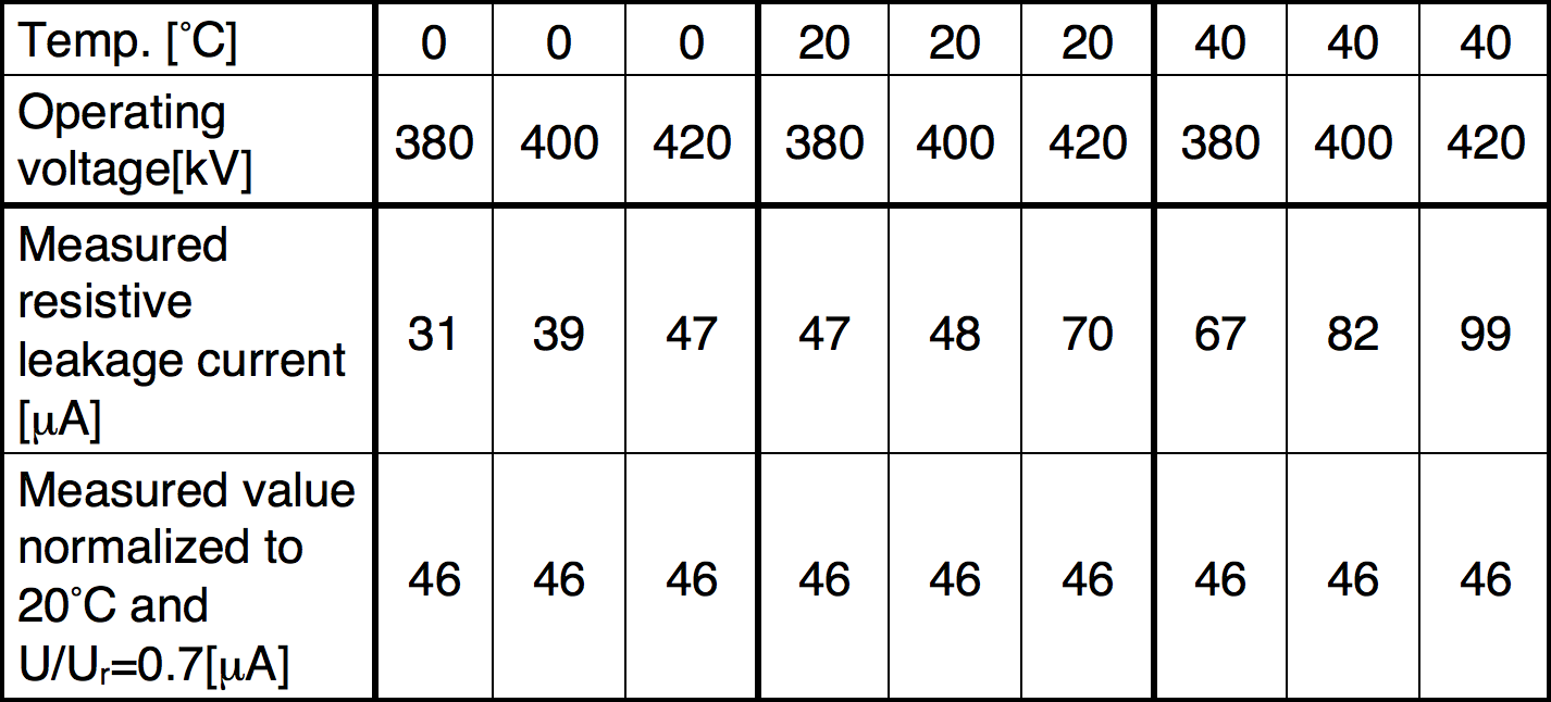
Influence of block temperature and operating voltage can be quite significant. For this reason, measuring both is recommended. Ambient temperature measurements can be used to estimate block temperature by keeping in mind that the time constant for temperature changes of blocks is a few hours. Doing so allows recalculating measured values of the resistive leakage current – referred to as so-called standard reference conditions, i.e. to an ambient temperature of 20°C and an operating voltage 0.7 times the rated voltage. This way, measurements performed at different temperatures and/or operating voltages can be directly compared. Table 1 illustrates variations of the leakage current with temperature and operating voltage for the same condition of a specific MOSA in the case of a 420 kV system. For instance, if two measurements have been performed at ambient temperatures of 0°C and 40°C and the same voltage respectively, the actual measured values might deviate by more than 100% relative to one another. This would be the case even though the normalized values at 20°C should be the same as long as the arrester’s condition is unchanged.
Risk Assessment & Testing Strategy
In the case of MOSAs, the best practice of risk assessment is based on the trend and level of the resistive leakage current under standard reference conditions. If the resistive leakage current exceeds a certain threshold value, the following steps should be taken in final evaluation/judgement:
1. If the resistive leakage current is unrealistically high (i.e. in the mA range and many times higher than for MOSAs of the same type), check that the arrester base and earth lead are properly insulated from the pedestal. If the arrester base is non-insulated, circulating currents will be induced in the earth system and cause incorrect measurements of leakage current.
2. Consider re-testing the MOSA in one or two days to confirm the high reading. If confirmed, proceed to steps 3 or 4. The reason for re-testing is that the MOSA could have been subjected to a transient overvoltage causing a higher current for several hours due to the energy absorbed.
3. Monitor the MOSA continually to follow the development of resistive leakage current. If this increases from its already high level, proceed to step 4.
4. Contact the manufacturer and consider replacing the arrester.

The threshold value for resistive leakage current will vary from arrester to arrester, depending on type, and can be established in different ways. Some manufacturers provide so-called ‘maximum recommended levels’ for the resistive leakage current for each type of arrester. When such values are given, the corrected values for resistive leakage current can be compared directly to maximum recommended levels (which could be in the range of 100-500 µA, depending on type). If maximum recommended resistive leakage current values are not available from the manufacturer, risk assessment or threshold values for that particular type of arrester can be established based on experience, as follows:
• Measure the resistive leakage current just after commissioning and use this as the arrester’s baseline reading. If the leakage current eventually increases by a factor larger than 3 to 4 times this baseline value, this is indicative of severe ageing.
• Make an individual comparison of all three arresters of the same type in a three-phase configuration. If one shows consistently and significantly higher levels than the other two, this might indicate ageing.
• Compare the resistive leakage currents in all arresters of the same type in the grid: Firstly, if one or a few arresters show significantly higher levels than the others of the same type, this may indicate ageing and requires closer follow-up. Secondly, if a number of arresters show low values at the same level, these may be used as good/acceptable levels for this type of arrester. Thirdly, if one or more arresters have been in service for only a couple of years, the measured values are expected to be close to baseline readings.
In general, MOSAs should ideally be tested subsequent to any unusual fault situations as well as after periods with especially difficult climatic or pollution conditions affecting the grid. In this regard, the following strategy is recommended (but can be modified based on local experience):
1. Classify and identify all arresters (name of substation, bay/line and phase, nameplate data, manufacturer, type designation, year/date of commissioning etc., historical data/failure rates, importance etc.);
2. Establish threshold levels/maximum recommended levels for the resistive leakage current for each type;
3. Define action limits (e.g. good condition, re-test/monitor continuously, replace);
4. Define measurement frequency (e.g. normal, often, continuous monitoring, or only after special fault situations);
5. Define verification actions after replacement (laboratory test, dissection/inspection);
6. Evaluate measurements, action limits, regularity of measurements and verification tests to optimize test strategy.

Conclusions
Leakage current measurements based on THRC have proven a reliable and efficient methodology to assess the service condition of gapless metal oxide surge arresters, in accordance with IEC recommendations. Implementing a testing strategy for substation arresters in the grid will not only optimize their lifetime utilization but also ensure that bad or aged arresters are replaced before they fail. This will contribute to increased reliability and safety while also eliminating the substantial costs associated with failure and unplanned outages.
[inline_ad_block]