Current protection systems for distribution networks are typically designed to handle fast-impulse overvoltages, such as from switching and lightning, but not power frequency overvoltages that are relatively long duration.
For example, should contact occur between a transmission and a distribution line or between distribution lines having different operating voltages, the higher voltage is transferred to the lower voltage line. Possible damage to the primary system can include breakdown of existing distribution class arresters and damage to transformers. The voltage spike being passed to the secondary system also risks damaging household electronic devices.
Methods to mitigate this problem are based mostly on preventing such contact. They can range from avoiding use of underbuilt structures in the first place to increasing transmission line tension or separation distance, to placement of a ground plane between nearby distribution and transmission lines.
A more cost-effective solution, however, involves applying station class arresters for lines that have underbuilt distribution. FortisBC in Canada and Dominion Virginia Power in the U.S. are two utilities that have successfully employed this concept to mitigate power frequency overvoltages. In the case of the Canadian utility, the main goal was dealing with transmission to distribution contact faults while Dominion was concerned mostly with contact faults between different distribution voltages. The experience for both is reported in this INMR article from 2013.
Types of Overvoltages
There are three main categories of overvoltage that can affect power systems: lightning, switching and power frequency – all with their own causes, consequences and ideal preventative measures.
Lightning
Lightning overvoltages, the most common cause of transient faults, arise when a lightning strike occurs on or near a power line. Resulting surges generally travel along the line at close to the speed of light causing line voltage to increase rapidly for a short duration. While lightning can cause temporary faults on distribution circuits, usually less than 20% of strikes lead to permanent damage. In certain cases, lightning strike can trigger a relatively long outage if it causes a fault that overloads the fuse in a cutout or locks out a recloser. The strategy generally used to protect against this type of event involves applying distribution class arresters to protect equipment susceptible to permanent damage by lightning as well as automatic reclosing to re-energize the circuit once the fault has been cleared.
Switching
A switching overvoltage is caused by operation of line switches to either energize or de-energize HV equipment. The arc generated as the switch opens or closes could lead to a high frequency transient voltage being superimposed over the power frequency. Switching overvoltages are also generally successfully controlled by arresters since, as with lightning overvoltage, they involve transient voltage spikes that can be mitigated the same way.
[inline_ad_1]
Power Frequency
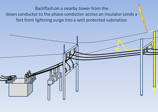
A power frequency overvoltage can result from direct contact between a transmission and distribution line or through contact between distribution lines with different operating voltages. Such events could occur, for example, on underbuilt structures should ice buildup weigh down one of the lines. Similarly, high winds can damage structures or falling trees can cause lines to touch.
Unlike for lightning and switching, the resulting power frequency overvoltage is of comparatively long duration, (i.e. tens of milliseconds). This presents problems for protection systems not typically intended to handle such an extended overvoltage. As discussed, the result can be failure of the protection devices and risk of damage to distribution and customer equipment.
CLICK TO ENLARGE
Effect on Utility & Customer Equipment
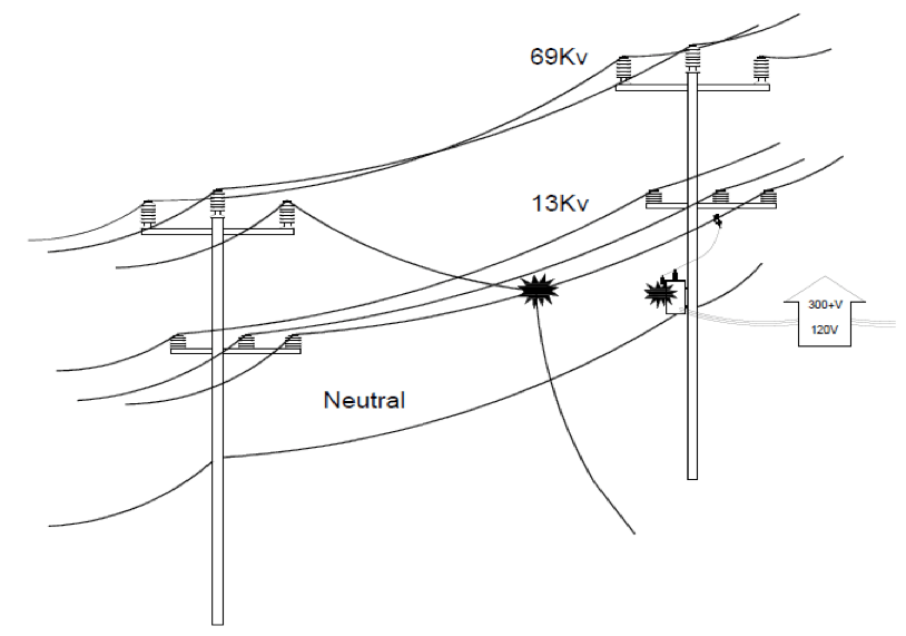
Overvoltage surges caused by line contact can increase distribution voltage to several times normal values. For example, contact of a 69 kV with a 13 kV line will raise the distribution feeder voltage by 5 times normal, resulting in 300+V on the secondary side of the distribution transformers near the fault. Such faults are typically lower magnitude but longer duration than lightning surges.
When a power frequency overvoltage occurs, distribution arresters transfer the surge to ground but immediately overload and become short to earth until the 69 kV breaker clears the event. But once the 69 kV line is reenergized, the distribution arresters, already out of the circuit, cannot transfer the second application of high voltage to ground. Some portion of the surge will then likely also be transferred to the secondary side of transformers, resulting in risk of damage to customer equipment.
Basically, the sequence of events in this case is as follows:
1. Accidental contact made
2. Distribution arresters clamp
3. Distribution arresters fail and disconnect
4. 69 kV breaker opens
5. 13.2 kV system normal
6. 69 kV breaker recloses
7. 32.2 kV system rises to 69 kV (distribution arresters that had previously clamped have all automatically disconnected from the circuit with their ground lead disconnectors and therefore do not clamp when the 69 kV voltage is re-applied)
8. secondary voltage rises to 300+ volts
Residential wiring insulation in North America is rated for 300 volts as per CSA standard and U.S. National Electrical Code, so it is unlikely that it would be compromised as a result of the surge. However, this momentary overvoltage surge potential can damage customers’ panels, equipment and appliances.
[inline_ad_2]
Mitigation Techniques for Power Frequency Overvoltage on Underbuilt Distribution Lines
1. Avoiding/Removing Underbuilt Structures
Avoiding the practice of underbuilding on transmission and distribution lines means more land would be required for line right-of-ways (often difficult to obtain) and increased construction and materials costs. Moreover, in those cases where transmission and distribution are already underbuilt over long distances, this is not really that feasible.
2. Installing More Distribution Class Surge Arresters
Another option is to install more distribution class arresters, in parallel, on underbuilt lines in order to clamp the voltage. However, the fault level and duration exceed these arrester’s typical design limit (normally 10 kA), leading to the circuit’s protection operating only a single time. Once the distribution arrester’s ground lead disconnects, it is removed from the circuit and leaves the transformer and customer electronics to bear the full surge during any restoration attempt of the transmission line.
3. Insulating Lower Circuit
Insulating and covering the lower circuit can be an option but is costly and has its challenges that relate to covered conductors, given their typical ageing problems. It is also difficult to apply on existing circuits.
4. Increasing Circuit Spacing
This is achieved by, as much as possible, specially designing common structures to minimize chance of faults between circuits or by using wider spacing between circuits. This would be especially suitable wherever snow and ice loading is the main cause of a power frequency fault. However, while this will reduce probability of conductors making contact, it will not eliminate all risk of a problem. Heavy objects, such as a tree falling on lines, or structural failure due to vehicle collision or severe weather could still result in a transmissionto- distribution or distribution-todistribution short.
[inline_ad_3]
5. Mid Grounding the Grid
Some countries have responded to the risk of such problems by further separating transmission and distribution segments or by moving the neutral wire from below both transmission and distribution to a middle point between them. This adds distance between the lines, without need for a larger pole, and also has the benefit of shorting any contact below the HV transmission line to ground since it would likely first contact the ground wire. One disadvantage to this solution, however, is that lower clearance from distribution lines to ground could pose a safety hazard. Moreover, major structural modifications may be required with incremental costs and time to implement.
6. Doing Nothing
Many utilities choose to do nothing and instead focus on dealing with the outcome of any incidents.
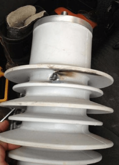
7. Implementing Station Class Arresters
Station class arresters effectively improve voltage protection during contact between lines since they are able to tolerate higher voltages over longer periods of time. They can have their specified maximum continuous operating voltage (MCOV) equal to that of distribution class arresters, while also being able to withstand much higher surge energy, as such reducing the impact of power frequency overvoltage on low voltage equipment. At the same time, larger MOV disks in such arresters add to the reliability of voltage control during other types of overvoltage events. Station class arresters do not come equipped with ground disconnects and do not isolate from ground during fault conditions.
[inline_ad_4]
Momentary transients due to lightning or switching will cause a station class arrester to conduct but do not damage the unit. By contrast, a power frequency overvoltage – because of its duration – will damage the arrester causing it to fail by being short-circuited. As there is no disconnecting fuse or isolator at the bottom, the circuit cannot be restored until the arrester is cut free or replaced. Fault indicators are therefore recommended in order to quickly find the location of failed station class arresters on the system.
Because of more robust design, station class arresters can be a cost effective measure for the mitigation of a power frequency overvoltage and improve overall system reliability. For example, below is the sequence of events should a e.g. 69 kV line contact a 13 kV line where station class arresters have been installed:
1. Contact made
2. Station class arrester absorbs fault energy, fails (sacrifices) and brings energy to earth, protecting distribution equipment and customers
3. 69 kV breaker opens
4. 13 kV system opens
5. 69 kV breaker recloses (normal)
6. 13 kV system closes and opens, i.e. phase-to-ground fault
7. FCI (fault current indicator) starts flashing
8. Crew goes to fault location to find damaged station class arrester and cuts ground lead (disconnect from the system) to enable power to be restored
The same sequence of events would basically apply in the case of contact between two distribution circuits of differing voltage.
Service Experience at FortisBC
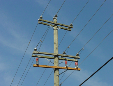
FortisBC provides electricity and gas to homes and businesses across the Canadian province of British Columbia. In 2010, with a focus on offering both safe and reliable energy, engineers chose to install station class arresters as pilot projects in two locations identified at high risk for overvoltage incidents. The correct placement of these arresters was regarded as crucial and key criteria in this regard were established:
• Installing station class arresters typically every 2 km along important under built distribution lines;
• Installing a station class arrester for every distribution tap phase;
• Avoiding placement on switching structures or where distribution transformers are on the main line; and
• Ensuring that structures where station class arresters are to be used have ample space for installation, inspection and maintenance.
CLICK TO ENLARGE
The objective was, as much as possible, to install the station class arresters close to high-density areas along the main line to protect greater numbers of customers. A site visit was conducted during the design stage to confirm placement according to these criteria. Construction standard drawings were then created and design packages completed based on system configuration and structure location.
In February of 2012, the first test of the installation occurred when snow uploading caused a transmission line to come into contact with the distribution underbuild. As expected, the station class arrester successfully absorbed the energy, ‘sacrificed itself’ and protected the system, with no reports of any customer damage.
CLICK TO ENLARGE
CLICK TO ENLARGE
Service Experience at Dominion Virginia Power
Dominion Virginia Power operates a 6300-mile network of regulated transmission lines and 56,800 miles of distribution lines serving 2.5 million homes and businesses in Virginia and North Carolina.
As far back as 2007, Dominion engineers were already thinking to experiment with applying station class arresters to protect underbuilt circuits. It was felt that a station class arrester had the ability to operate well before the limits of the ITIC curve and that a high energy station class arrester would stay intact and continue to divert fault energy to ground. The goal was to mitigate damage from overvoltage events, based on the concept whereby, if the arrester operated (i.e. shorted out) in response to sustained overvoltage, it would be replaced.
CLICK TO ENLARGE
The equipment needed for such an application was finalized that year for application on 13.2 kV and 12.5 kV circuits which were built below 34.5 kV distribution lines. They were the prime focus initially since past experience showed that most line contact cases on the Dominion network involved damage on underbuilt circuits with either of these two voltage levels. At the time, there were 13 overvoltage events that year across the utility’s distribution system and approximately 700 miles of exposed lines with dissimilar voltages.
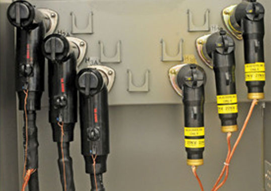
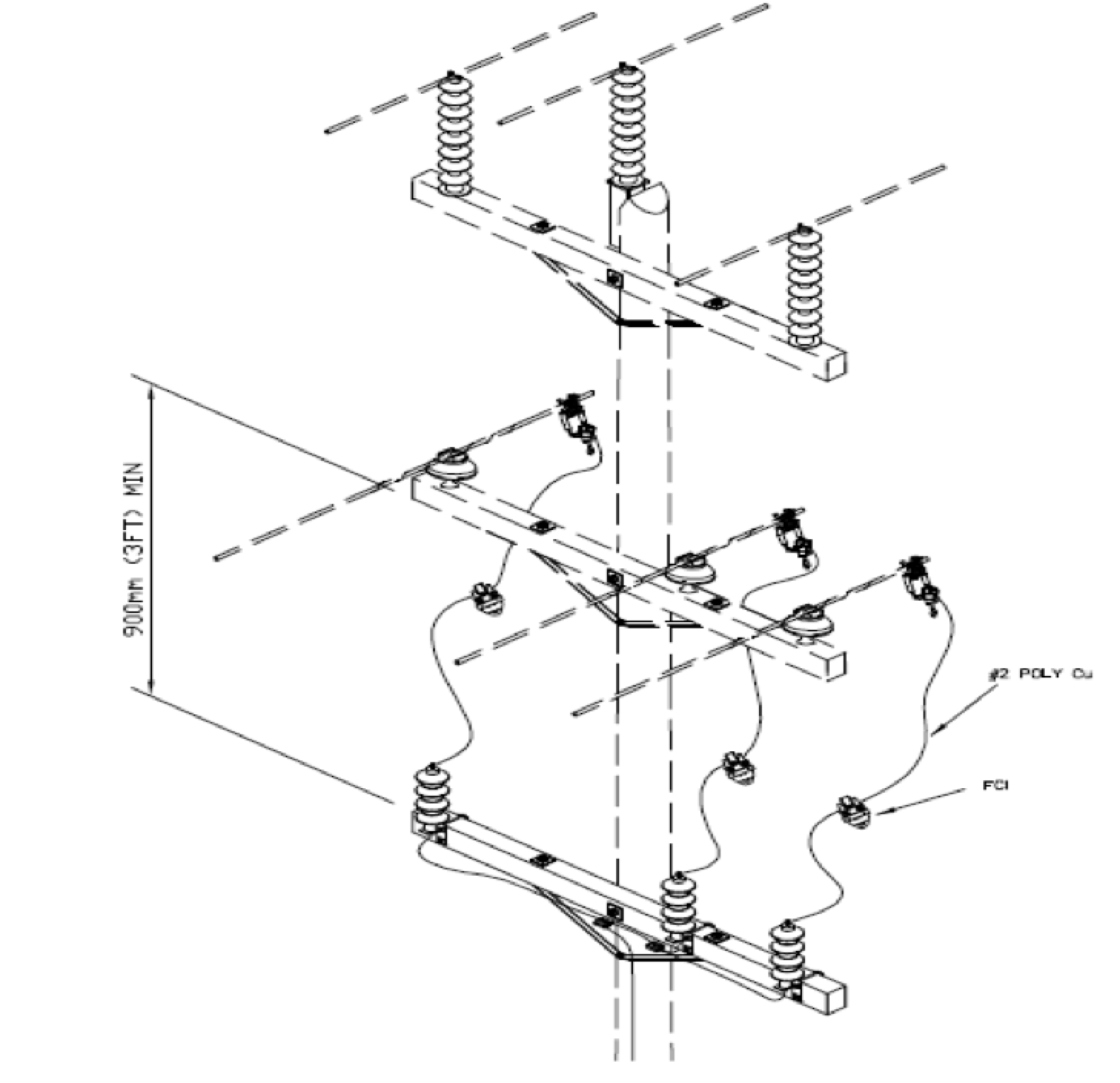
Station class arresters for 13.2 kV and 12.5 kV are relatively short. Therefore, to eliminate risk of errors during installation, wildlife guards were added along with covered line leads. In addition, faulted circuit indicators were added to arrester line leads to assist rapid restoration by pinpointing which units had operated.
To verify the concept, a 2-mile (3.2 km) section of a 34.5 kV line with a 13.2 kV underbuilt circuit was selected as a test case since it had already experienced a number of contacts between the circuits. Two sets of arresters were installed along the length of the underbuild: the first near the start and the second a mile (1.6 km) beyond. A second circuit of equal length and similar in many respects to the first was selected a month later and also had two sets of arresters installed.
CLICK TO ENLARGE
In 2008, just months after the first installation had been put into service, a vehicle accident caused the top phase of the first installation to fall and contact a lower phase.
Both arresters on that phase operated (shorted-out) and protected both customer and Dominion equipment. By this measure, the installation was judged a success and perhaps the first demonstration anywhere of a truly cost-effective means to protect underbuilt circuits.
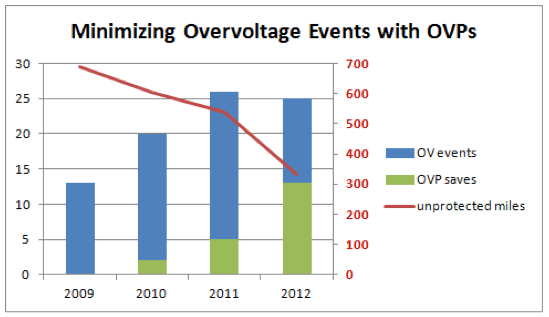
The second installation took longer to yield results but, some 2.5 years after being put into service, a tree limb caused contact between one phase of each circuit. Again, it was a success, this time with only one arrester handling the overvoltage. After this second event, this concept started to gain support within Dominion and soon demand for OVPs by field offices began to outstrip supply.
While the number of such overvoltage events increased from a low of 13 in 2007 to 25 in 2012, by that time the Dominion network had more than half its line exposure protected. There were 13 successful operations of OVPs that year, as would be expected given that level of coverage, and 2012 proved the most successful year since the program started. The expectation for 2013 is that all remaining unprotected lines will be protected before the end of the year.