[inline_ad_block]
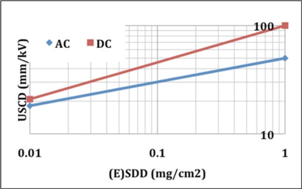
Design of insulation for DC transmission is much more demanding than for AC, particularly from the standpoint of pollution performance. Fig. 1 below, for example, derives from laboratory testing of ceramic insulators and plots unified specific creepage distance (USCD) required as a function of pollution severity, measured by salt deposit density (SDD). This relationship has since been confirmed by field experience. HVDC lines equipped with ceramic insulators designed according to the red curve will give good service performance while insulators designed with a lower USCD are likely to encounter problems of flashover. Also illustrated in the graph is the fact that, depending on pollution, DC lines may require insulation having a much larger USCD than for AC. This can result in unrealistic design parameters – especially when there is the combination of UHV and heavy contamination. In the extreme case of very high pollution (e.g. SDD of 1 mg/cm2), a total creepage distance of more than 90 meters would be required for 800 kV insulator strings. This would mean an astounding insulator length of some 27 m for insulators with a creepage factor (CF) of 3.4, as is the typical limit for DC applications.
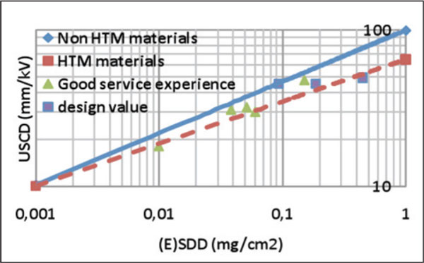
DC presents a much more severe design scenario for composite insulators as well. However such insulators benefit greatly from the hydrophobic transfer material (HTM) property of their polymeric weathersheds. In this regard, Fig. 2 depicts preliminary results of an analysis now going on within CIGRE WG C4.03.03. Basically, it shows that HTM insulators require a lower USCD at the same SDD than do insulators made from non-HTM materials. This is demonstrated not only by laboratory investigation (see the dotted curve in Fig. 2) but also by service experience (see points in Fig. 2 that refer to real HVDC lines). Based on Fig. 2, in the extreme case of very heavy contamination (e.g. SDD of 1 mg/cm2), 52 m of creepage would be sufficient for an 800 kV composite insulator set. The corresponding insulator length could therefore be “only about 14 m”, mainly because composite insulators work more efficiently at the higher CF (assumed to be 3.8 in this case against a 3.4 value for cap & pin ceramic).
CLICK TO ENLARGE
CLICK TO ENLARGE
Now, to be fair, this is just an example that makes reference to extreme pollution conditions that are rare in actual practice. The goal here is only to qualitatively emphasize the criticality of insulation design parameters and to demonstrate the comparative advantage offered by composites. Due to feasibility aspects and the cost impact of pollution in DC, insulation design should be very detailed. This will require accurately assessing site contamination severity by means of measurements on energized insulators while also carrying out laboratory tests to assess performance of the insulators selected. Such performance will depend greatly on profile and characteristics (i.e. the curves shown in Fig. 1 and 2 represent only a sort of average performance). A statistical design approach can then be applied by assigning some acceptable risk of flashover.
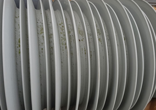
Two of the most important aspects of insulators for DC application are housing material and profile. As far as the first is concerned, a tracking and erosion test is standardized for AC (IEC 60587) but there is still debate within CIGRE WG D1.26 and IEC 36 as to whether a similar test is necessary for DC (or if the same AC material ranking can be applied).
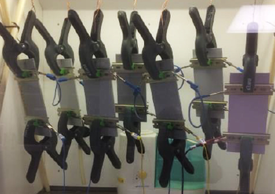
In this regard, several tracking and erosion investigations were conducted in different part of the world applying a DC stress equal to that of ACrms. These tests have shown that DC is indeed more severe in this respect than AC. However, in my opinion, such tests are inherently biased and their conclusions should not be considered valid from a practical perspective. This view is confirmed by the satisfactory service experience of insulators presently installed on HVDC lines and also by laboratory experience obtained by long-term ageing tests on different makes of insulators that were correctly scales according to the AC/DC stress ratio.
As can be derived from Fig. 1 (which can be extended to composite insulators by taking into consideration their HTM benefit), insulators will not encounter the same service stress in AC as in DC. Depending on pollution severity, the DC stress can be as little as half that of AC. Therefore, if a tracking test is to be standardized and made realistic for DC, it should take this into account. Moreover, optimization of insulator geometry in DC will have to consider that creepage distance loses its efficiency in the case of too narrow a profile and too high a CF factor, with more stringent limits than is the case for AC.